Nissan Sentra Service Manual: Unit disassembly and assembly
TRANSAXLE ASSEMBLY
Exploded View
CASE AND HOUSING
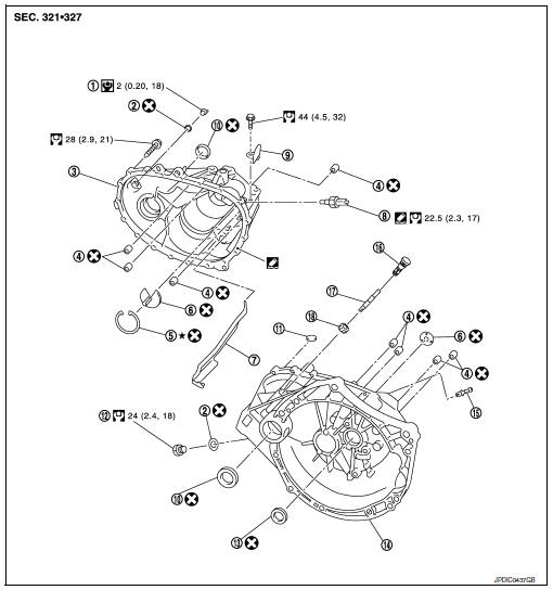
- Filler plug
- Gasket
- Transaxle case
- Bushing
- Snap ring
- Oil channel
- Oil gutter
- Position switch
- Bracket
- Differential side oil seal
- Magnet
- Drain plug
- Input shaft oil seal
- Clutch housing
- 2 way connector
- Plug
- Pinion shaft
- Pinion gear
Shaft and gear
- Input shaft front bearing
- Input shaft
- 3rd input gear
- Spacer
- Snap ring
- 3rd baulk ring
- 3rd-4th coupling sleeve
- 3rd-4th synchronizer hub
- Insert key
- 4th baulk ring
- 4th input gear
- 5th input gear
- 5th baulk ring
- 5th-6th coupling sleeve
- 5th-6th synchronizer hub
- 6th baulk ring
- Needle bearing
- 6th input gear
- Input shaft rear bearing
- First step
- Final step
- Mainshaft front bearing outer race
- Mainshaft front bearing inner race
- Mainshaft
- 1st main gear
- 1st inner baulk ring
- 1st synchronizer cone
- 1st outer baulk ring
- 1st-2nd coupling sleeve
- Insert key
- 1st-2nd synchronizer hub
- 2nd outer baulk ring
- 2nd synchronizer cone
- 2nd inner baulk ring
- 2nd main gear
- Bushing
- 3rd main gear
- Mainshaft adjusting shim
- 4th main gear
- 5th main gear
- 6th main gear
- Mainshaft rear bearing inner race
- Mainshaft rear bearing outer race
- Snap ring
- Mainshaft rear bearing adjusting shim

- Reverse output gear
- Snap ring
- Reverse baulk ring
- Return spring
- Needle bearing
- Seal washer
- Reverse idler shaft
- Spacer
- Reverse input gear
- Lock washer
- Spring washer
Shift fork and fork rod
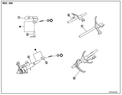
- Shifter lever A
- Shifter lever B
- Retaining pin
- Selector
- Selector lever
- Reverse fork rod
- 1st-2nd fork rod
- Fork rod
Final drive
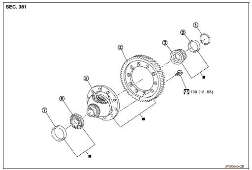
- Shim
- Differential side bearing outer race (transaxle case side)
- Differential side bearing inner race (transaxle case side)
- Final gear
- Differential case
- Differential side bearing inner race (clutch housing side)
- Differential side bearing outer race (clutch housing side)
Disassembly
- Remove drain plug and gasket from clutch housing, using a suitable tool and drain gear oil.
- Remove filler plug and gasket from transaxle case.
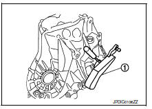
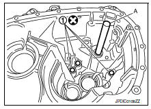
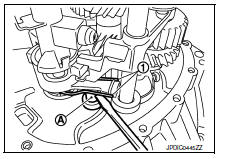
- Remove selector lever (1) retaining pin with a pin punch to remove selector lever.
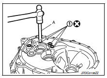
- Remove bracket (2) and position switch (3) from transaxle case.
- Remove transaxle case bolts (
 ).
).
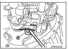
- Remove reverse idler shaft bolt (
) and sealing washer.
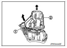
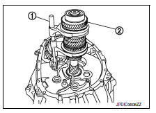
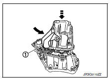
- Remove transaxle case (2) while rotating shifter lever a (1) in the direction as shown.
- Remove selector spring (1) from return bushing (a).
- Shift 1st-2nd fork rod (1), fork rod (2), and reverse fork rod (3) to the neutral position.
- Remove selector (4) from clutch housing.
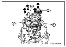
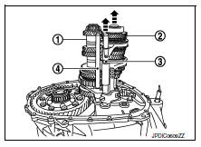
- Remove reverse idler shaft assembly (1), with the following procedure.
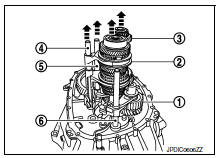
- Pull up input shaft assembly (2), mainshaft assembly (3), fork rod (4), and 1st-2nd fork rod (5).
Note:
It is easier to pull up when shifting each fork rod to each shaft side.
- Remove reverse idler shaft assembly and reverse fork rod (6) from clutch housing
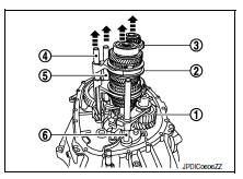
- Remove spring washer from clutch housing.
- Pull up and remove input shaft assembly (1), mainshaft assembly (2), fork rod (3), and 1st-2nd fork rod (4) from clutch housing.
Note:
It is easier to pull up when shifting each fork rod to each shaft side.
- Remove final drive assembly (1) from clutch housing.
- Remove magnet from clutch housing.
- Remove differential side oil seals (1) from clutch housing and transaxle case.
Caution:
Do not damage clutch housing and transaxle case.
Do not reuse differential side oil seal.
- Remove differential side bearing outer race (1) from clutch housing, using a suitable tool.
Caution:
Do not damage clutch housing.
- Remove differential side bearing outer race (1) from transaxle case, using a suitable tool.
Caution:
Do not damage transaxle case.
- Remove shim (2) from transaxle case.
- Remove shifter lever a (1) retaining pin, using a suitable tool.
Caution:
Do not reuse retaining pin.
- Remove shifter lever a from transaxle case.
- Remove shifter lever B (1) from transaxle case.
- Remove oil gutter (1) from transaxle case.
- Remove bushings (1) from transaxle case, using a suitable tool.
Caution:
Do not reuse bushings.
- Remove mainshaft rear bearing outer race from transaxle case, using a suitable tool.
- Remove mainshaft rear bearing adjusting shim from transaxle case.
- Remove snap ring (1) and oil channel (2) from transaxle case.
Caution:
Do not reuse snap ring or oil channel.
- Remove input shaft oil seal (1) from clutch housing, using a suitable tool.
Caution:
Do not damage clutch housing.
Do not reuse input shaft oil seal.
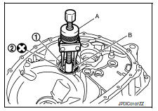
- Remove mainshaft front bearing outer race (1) from clutch housing, using Tool (A) and a suitable tool (B).
Tool number (a) : kv381054s0 (j-34286)
- Remove oil channel (2) from clutch housing.
Caution:
Do not reuse oil channel.
- Remove bushings (1) from clutch housing, using a suitable tool.
Caution:
Do not reuse bushings.
- Remove 2 way connector (1) from clutch housing.
Assembly
- Install 2 way connector (1) to clutch housing.
- Install bushings (1) so that they becomes even with clutch housing surface, using suitable tool (A).
- Install oil channel to clutch housing.
CAUTION:
Do not reuse oil channel.
- Install mainshaft front bearing outer race to clutch housing using Tool (A).
CAUTION:
Replace mainshaft front bearing outer race and mainshaft front bearing inner race as a set.
Do not reuse mainshaft front bearing inner or outer race.
Tool number (A) : KV38100200 ( — )
- Install input shaft oil seal (1) to clutch housing using the Tool (A).
Tool number (A) : ST33220000 ( — )
- Install snap ring (1) and oil channel (2) to transaxle case.
CAUTION:
- Select and install snap ring that has the same thickness as previous one.
- Replace transaxle assembly when replacing transaxle case.
- Install mainshaft rear bearing adjusting shim to transaxle case.
CAUTION:
Select mainshaft rear bearing adjusting shim, with the following procedure when replacing mainshaft adjusting shim, 6th main gear, 5th main gear, or 4th main gear.
- Replace mainshaft adjusting shim.
- If new mainshaft adjusting shim is thinner than previous one, offset the thickness difference by selecting thicker mainshaft rear bearing adjusting shim.
- If new mainshaft adjusting shim is thicker than previous one, offset the thickness difference by selecting thinner mainshaft rear bearing adjusting shim.
- Replace 6th main gear, 5th main gear, or 4th main gear.
- Measure the thickness of the main gear used before and the new main gear
- Increase the thickness of the mainshaft rear bearing adjusting shim, if the difference is smaller than 0.025 mm (0.0010 in).
- Decrease the thickness of the mainshaft rear bearing adjusting shim, if the difference is greater than 0.025 mm (0.0010 in).
- Install mainshaft rear bearing outer race to transaxle case using suitable tool (A).
CAUTION:
Replace mainshaft rear bearing outer race and mainshaft rear bearing inner race as a set.
Tool number : KV38100200 ( — )
- Install bushings (1) to transaxle case, using suitable tool (A).
- Install oil gutter (1) to transaxle case.
- Install shifter lever B (1) to transaxle case.
CAUTION:
Replace shifter lever A and shifter lever B as a set.
- Install shifter lever A to transaxle case.
CAUTION:
Replace shifter lever A and shifter lever B as a set.
- Install retaining pin to shifter lever A (1) using a suitable tool.
CAUTION:
Do not reuse retaining pin.
- Install shim to transaxle case.
- Install differential side bearing outer race (transaxle case side) to transaxle case, using Tool (A).
CAUTION:
Replace differential side bearing outer race (transaxle case side) and differential side bearing inner race (transaxle case side) as a set.
Do not reuse differential side bearing inner or outer race.
Tool number : ST33400001 (J-26082)
- Install differential side bearing outer race (clutch housing side) to clutch housing, using Tool (A).
CAUTION:
Replace differential side bearing outer race (clutch housing side) and differential side bearing inner race (clutch housing side) as a set.
Do not reuse differential side bearing inner or outer race.
Tool number : KV38100200 ( — )
- Install differential side oil seals (1) to clutch housing and transaxle case, using Tools.
Tool number : KV32500QAA
Tool number : B.vi 1666-B
(A) : Transaxle case side
(B) : Clutch housing side
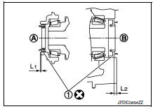
Dimension (L1) : 1.2 – 1.8 mm (0.047 – 0.071 in)
Dimension (L2) : 2.7 – 3.3 mm (0.106 – 0.130 in)
CAUTION:
- Do not incline differential side oil seal.
- Do not damage clutch housing and transaxle case.
- Install magnet to clutch housing.
- Install final drive assembly to clutch housing.
- Set fork rod (1) to input shaft assembly (2), and then install them to clutch housing.
- Install mainshaft assembly (1), with the following procedure.
- Pull up input shaft assembly (2) and fork rod (3).
- Set 1st-2nd fork rod (4) to mainshaft assembly and install them to clutch housing.
- Install reverse idler shaft assembly (1) with the following procedure.
- Install spring washer to clutch housing.
- Pull up input shaft assembly (2), mainshaft assembly (3), fork rod (4), and 1st-2nd fork rod (5).
NOTE:
It is easier to pull up when shifting each fork rod to each shaft side.
- Set reverse fork rod (6) to reverse idler shaft assembly and install them to clutch housing.
- Move 1st-2nd fork rod (1), fork rod (2), and reverse fork rod (3) to the neutral position.
- Install selector (4) to clutch housing.
CAUTION:
Replace selector lever and selector as a set.
- Install selector spring (1) to return bushing (A).
- Apply recommended sealant to the gasket surface of transaxle case.
- Use Genuine Silicone RTV or an equivalent. Refer to GI- 21, "Recommended Chemical Products and Sealants".
CAUTION:
- Do not allow old liquid gasket, moisture, oil, or foreign matter to remain on gasket surface.
- Check that the gasket surface is not damaged.
- Apply sealant bead continuously.
- Install transaxle case to clutch housing while rotating shifter lever A (1) in the direction as shown.
- Install reverse idler shaft bolt (
 ), as per the following
procedure.
- Install sealing washer to reverse idler shaft bolt, and install reverse idler shaft bolt to transaxle case.
CAUTION:
Do not reuse sealing washer.
- Tighten reverse idler shaft bolt to the specified torque.
- Tighten transaxle case bolts (
) to the specified torque.
- Install position switch (1), with the following procedure.
- Apply recommended sealant to threads of position switch.
- Use Genuine Silicone RTV or an equivalent.Refer to GI-21, "Recommended Chemical Products and Sealants".
CAUTION:
Do not allow old liquid gasket, moisture, oil, or foreign matter to remain on thread.
- Install position switch to transaxle case and tighten it to the specified torque.
- Install bracket (2) to transaxle case and tighten bolt to the specified torque.
- Install selector lever (3) with the following procedure.
- Install selector lever to transaxle case.
CAUTION:
Replace selector lever and selector as a set.
- Install retaining pin to selector lever using a suitable tool.
CAUTION:
Do not reuse retaining pin.
- Install drain plug with the following procedure.
- Install gasket to drain plug.
CAUTION:
Do not reuse gasket.
- Install drain plug to clutch housing using a suitable tool.
- Tighten drain plug to the specified torque.
CAUTION:
Do not overtighten drain plug as this could cause the transaxle case to crack.
- Install filler plug with the following procedure.
- Install gasket to filler plug and install it to the transaxle case.
CAUTION:
Do not reuse gasket.
- Tighten filler plug to the specified torque.
CAUTION:
Fill with gear oil before tighten filler plug to the specified torque.
Do not overtighten the filler plug as this could cause the transaxle case to crack.
Inspection
INSPECTION AFTER DISASSEMBLY
Check contact surface ( ) and
) and
sliding surface (  ) for excessive
wear, uneven wear, bend, and damage. Replace if necessary.
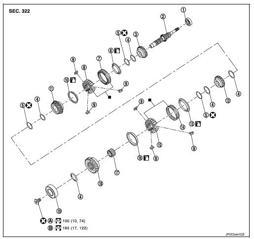
Input shaft and gear
Exploded View

- Input shaft front bearing
- Input shaft
- 3rd input gear
- Spacer
- Snap ring
- 3rd baulk ring
- 3rd-4th coupling sleeve
- 3rd-4th synchronizer hub
- Insert key
- 4th baulk ring
- 4th input gear
- 5th input gear
- 5th baulk ring
- 5th-6th coupling sleeve
- 5th-6th synchronizer hub
- 6th baulk ring
- Needle bearing
- 6th input gear
- Input shaft rear bearing
- First step
- Final step
Disassembly
CAUTION:
- Fix input shaft in a vise with back plate, and then remove gears and snap rings.
- For removal of snap ring, set snap ring pliers and flat pliers at both sides of snap ring. While expanding snap ring with snap ring pliers, move snap ring with flat pliers.
- Disassemble gear components putting direction marks on the parts that do not affect any functions.
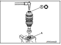
- Remove input shaft rear bearing bolt (1), using Tool (A).
CAUTION:
Do not reuse rear bearing bolt.
Tool number (A) : KV32300QAM ( — )
- Remove input shaft rear bearing (1) with the following procedure.
- Set a suitable tool to input shaft rear bearing.
- Remove input shaft rear bearing using suitable tool (A).
- Remove spacer (1), 6th input gear (2), needle bearing, 6th baulk ring, and 5th-6th synchronizer hub assembly (3).
- Remove insert keys and 5th-6th coupling sleeve from 5th-6th synchronizer hub.
- Remove snap ring (1).
CAUTION:
Do not reuse snap ring.
- Remove spacer, 5th baulk ring, 5th input gear (2), and spacer.
- Remove snap ring (1).
CAUTION:
Do not reuse snap ring.
- Remove spacer, 4th input gear (2), 4th baulk ring, and 3rd-4th synchronizer hub assembly (3).
- Remove insert keys and 3rd-4th coupling sleeve from 3rd-4th synchronizer hub.
- Remove snap ring (1).
CAUTION:
Do not reuse snap ring.
- Remove spacer, 3rd baulk ring, and 3rd input gear (2).
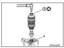
- Set a suitable tool to input shaft front bearing (1), and then remove input shaft front bearing.
Assembly
Assembly is in the reverse order of disassembly.
CAUTION:
- Replace transaxle assembly when replacing input shaft.
- For installation of snap ring, set snap ring pliers and flat pliers at both sides of snap ring. While expanding snap ring with snap ring pliers, move snap ring with flat pliers.
- Do not reuse snap ring.
- Check that snap ring is securely installed in a groove.
- Replace 3rd-4th coupling sleeve and 3rd-4th synchronizer hub as a set.
- Replace 5th-6th coupling sleeve and 5th-6th synchronizer hub as a set.
- Be careful to install 3rd-4th synchronizer hub according to the specified direction.
- 3rd input gear side
- 4th input gear side
- Be careful to install 5th-6th synchronizer hub according to the specified direction.
- 5th input gear side
- 6th input gear side
- Install input shaft front bearing (1) using a suitable tool (A).
- Install input shaft rear bearing (1) using a suitable tool (A) and Tool (B).
Tool number : ST36720030 ( — )
- Apply gear oil to 3rd baulk ring, 4th baulk ring, 5th baulk ring, and 6th baulk ring.
- Install input shaft rear bearing bolt (1), as per the following procedure.
CAUTION:
Follow the procedures. Otherwise it may cause a transaxle malfunction.
Do not reuse rear bearing bolt.
- Fix the Tool (A) in a vise and set input shaft assembly.
Tool number : KV32300QAM ( — )
- Install input shaft rear bearing bolt and tighten it to the specified torque of the first step.
- Loosen input shaft rear bearing bolt by a half turn.
- Tighten input shaft rear bearing bolt to the specified torque of the final step.
Inspection
INSPECTION AFTER DISASSEMBLY
Input Shaft and Gear
Check the following items and replace if necessary.
- Damage, peeling, bend, uneven wear, and distortion of shaft.
- Excessive wear, damage, and peeling of gear.
Synchronizer Hub and Coupling Sleeve
Check the following items and replace if necessary.
- Breakage, damage, and unusual wear on contact surface of coupling sleeve, synchronizer hub, and insert key.
- Coupling sleeve and synchronizer hub move smoothly.
Baulk Ring
Check contact surface of baulk ring cam and insert key for excessive wear, uneven wear, bend, and damage. Replace if necessary.
Check bearing for damage and uneven rotation. Replace if necessary.
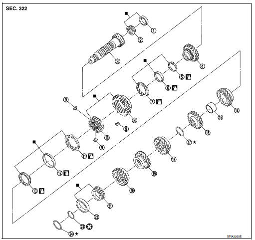
Mainshaft and gear
Exploded View
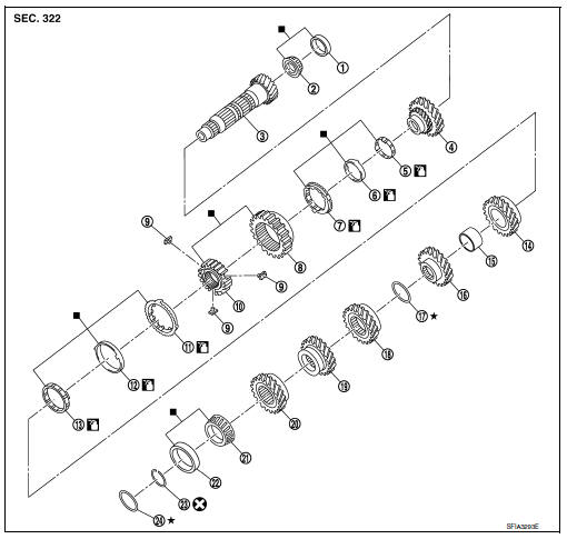
- Mainshaft front bearing outer race
- Mainshaft front bearing inner race
- Mainshaft
- 1st main gear
- 1st inner baulk ring
- 1st synchronizer cone
- 1st outer baulk ring
- 1st-2nd coupling sleeve
- Insert key
- 1st-2nd synchronizer hub
- 2nd outer baulk ring
- 2nd synchronizer cone
- 2nd inner baulk ring
- 2nd main gear
- Bushing
- 3rd main gear
- Mainshaft adjusting shim
- 4th main gear
- 5th main gear
- 6th main gear
- Mainshaft rear bearing inner race
- Mainshaft rear bearing outer race
- Snap ring
- Mainshaft rear bearing adjusting shim
Disassembly
CAUTION:
- Fix mainshaft in a vise with back plate, and then remove gears and snap rings.
- For removal of snap ring, set snap ring pliers and flat pliers at both sides of snap ring. While expanding snap ring with snap ring pliers, move snap ring with flat pliers.
- Disassemble gear components putting direction marks on the parts that never affect any functions.
- Remove snap ring (1).
CAUTION:
Do not reuse snap ring.
- Remove 6th main gear (1) and mainshaft rear bearing inner race (2), with the following procedure.
- Set a suitable tool to 6th main gear.
- Remove mainshaft rear bearing inner race and 6th main gear, using Tool (A).
Tool number : ST33052000 ( — )
- Remove 4th main gear (1) and 5th main gear (2) with the following procedure.
- Set a suitable tool to 4th main gear.
- Remove 5th main gear and 4th main gear, using Tool (A).
Tool number : ST33052000 ( — )
- Remove mainshaft adjusting shim.
- Remove 1st main gear (1), 1st-2nd synchronizer hub assembly (2), 2nd main gear (3), and 3rd main gear (4) with the following procedure.
- Set a suitable tool to 1st main gear.
- Remove 3rd main gear, busing, 2nd main gear, 2nd inner baulk ring, 2nd synchronizer cone, 2nd outer baulk ring, 1st-2nd synchronizer hub assembly, 1st outer baulk ring, 1st synchronizer cone, 1st inner baulk ring, and 1st main gear using Tool (A).
Tool number : ST33052000 ( — )
Tool number : ST33052000 ( — )
- Remove insert keys and 1st-2nd coupling sleeve from 1st-2nd synchronizer hub.
- Remove mainshaft front bearing inner race (1) with the following procedure.
- Set a suitable tool to mainshaft front bearing inner race.
- Remove mainshaft front bearing inner race using Tool (A).
Tool number : ST33052000 ( — )
Assembly
CAUTION:
- Select mainshaft rear bearing adjusting shim, as per the following procedure when replacing mainshaft adjusting shim, 6th main gear, 5th main gear, or 4th main gear.
- Replace mainshaft adjusting shim.
- If new mainshaft adjusting shim is thinner than previous one, offset the thickness difference by selecting thicker mainshaft rear bearing adjusting shim.
- If new mainshaft adjusting shim is thicker than previous one, offset the thickness difference by selecting thinner mainshaft rear bearing adjusting shim.
- Replace 6th main gear, 5th main gear, or 4th main gear.
- Measure the thickness of the main gear used before and the new main gear
- Increase the thickness of the mainshaft rear bearing adjusting shim, if the difference is smaller than 0.025 mm (0.0010 in).
- Replace transaxle assembly when replacing mainshaft.
- For installation of snap ring, set snap ring pliers and flat pliers at both sides of snap ring. While expanding snap ring with snap ring pliers, move snap ring with flat pliers.
- Do not reuse snap ring.
- Install mainshaft front bearing inner race (1) using Tool (A).
CAUTION:
Replace mainshaft front bearing outer race and mainshaft front bearing inner race as a set.
Do not reuse mainshaft front bearing inner or outer race.
Tool number : ST36720030 ( — )
- Apply gear oil to 1st inner baulk ring, 1st synchronizer cone, 1st outer baulk ring, 2nd inner baulk ring, 2nd synchronizer cone, and 2nd outer baulk ring.
CAUTION:
- Replace 1st inner baulk ring, 1st synchronizer cone, and 1st outer baulk ring as a set.
- Replace 2nd inner baulk ring, 2nd synchronizer cone, and 2nd outer baulk ring as a set.
- Install insert keys and 1st-2nd coupling sleeve to 1st-2nd synchronizer hub.
CAUTION:
Replace 1st-2nd synchronizer hub and 1st-2nd coupling sleeve as a set.
Install 1st main gear (1), 1st inner baulk ring, 1st synchronizer cone, 1st outer baulk ring, 1st-2nd synchronizer hub assembly (2), 2nd inner baulk ring, 2nd synchronizer cone, and 2nd outer baulk ring.
- Install bushing (3) using Tool (A).
Tool number : ST32102700 ( — )
- Install 3rd main gear (1) and 2nd main gear (2) using Tool (A).
Tool number : KV32102700 ( — )
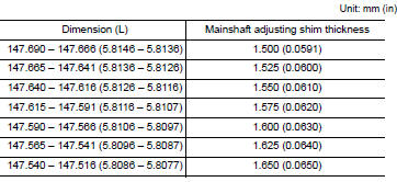
- Measure dimension (L) as shown in the figure. Select mainshaft adjusting shim (1) according to the following list, and then install it to mainshaft.
- Mainshaft
- 3rd main gear
- Install 4th main gear (1) using Tool (A).
Tool number : KV32102700 ( — )
- Install 5th main gear (1) using Tool (A).
Tool number : KV32102700 ( — )
- Install 6th main gear (1) using Tool (A).
Tool number : KV32102700 ( — )
- Install mainshaft rear bearing inner race (1) using Tool (A).
CAUTION:
Replace mainshaft rear bearing inner race and mainshaft rear bearing outer race as a set.
Tool number : ST30901000 (J-26010-01)
- Install snap ring.
CAUTION:
Do not reuse snap ring.
Inspection
INSPECTION AFTER DISASSEMBLY
Mainshaft and Gear
Check the following items and replace if necessary.
- Damage, peeling, bend, uneven wear, and distortion of shaft.
- Excessive wear, damage, and peeling of gear.
Synchronizer Hub and Coupling Sleeve
Check the following items and replace if necessary.
- Breakage, damage, and unusual wear on contact surface of coupling sleeve, synchronizer hub, and insert key.
- Coupling sleeve and synchronizer hub move smoothly.
Baulk Ring
Check contact surface of baulk ring cam and insert key for excessive wear, uneven wear, bend, and damage. Replace if necessary.
Bearing
Check bearing for damage and uneven rotation. Replace if necessary.
CAUTION:
- Replace mainshaft front bearing outer race and mainshaft front bearing inner race as a set.
- Replace mainshaft rear bearing inner race and mainshaft rear bearing outer race as a set.
Reverse idler shaft and gear
Exploded View
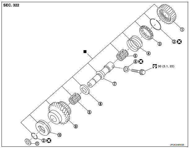
- Reverse output gear
- Snap ring
- Reverse baulk ring
- Return spring
- Needle bearing
- Seal washer
- Reverse idler shaft
- Spacer
- Reverse input gear
- Lock washer
- Spring washer
Disassembly
- Remove reverse output gear (1).
- Remove snap ring (1).
CAUTION:
Do not reuse snap ring.
- Remove reverse baulk ring (1) and return spring (2).
- Remove snap ring (1), lock washer (2), and reverse input gear (3).
CAUTION:
Do not reuse snap ring.
- Remove needle bearings (1) and washer.
Assembly
Assembly is in the reverse order of disassembly.
CAUTION:
- Do not reuse snap ring.
- Check that snap ring is securely installed in a groove.
- Replace reverse output gear, snap ring, reverse baulk ring, return spring, needle bearing, reverse idler shaft, spacer, reverse input gear, and lock washer as a set.
Inspection
INSPECTION AFTER DISASSEMBLY
Shaft and Gear
Check the following items. Replace reverse output gear, snap ring, reverse baulk ring, return spring, needle bearing, reverse idler shaft, spacer, reverse input gear, and lock washer as a set, if necessary.
- Damage, peeling, bend, uneven wear, and distortion of shaft
- Excessive wear, damage, and peeling of gear
Bearing
Check damage and rotation of bearing. Replace reverse output gear, snap ring, reverse baulk ring, return spring, needle bearing, reverse idler shaft, spacer, reverse input gear, and lock washer as a set, if necessary.
Final drive
Exploded View
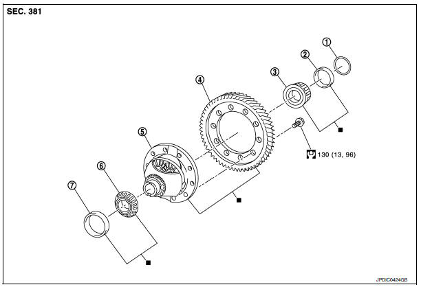
- Shim
- Differential side bearing outer race (transaxle case side)
- Differential side bearing inner race (transaxle case side)
- Final gear
- Differential case
- Differential side bearing inner race (clutch housing side)
- Differential side bearing outer race (clutch housing side)
Disassembly
- Remove differential side bearing inner race (clutch housing side) (1) with the following procedure.
- Set a suitable tool to differential side bearing inner race (clutch housing side).
- Remove differential side bearing inner race (clutch housing side) using Tool (A).
Tool number : ST33061000 (J-8107-2)
- Remove final gear mounting bolts and remove final gear (1).
- Remove differential side bearing inner race (transaxle case side) (1) with the following procedure.
- Set a suitable tool to differential side bearing inner race (transaxle case side).
- Remove differential side bearing inner race (transaxle case side) using a suitable tool (A).
Assembly
- Install final gear, and then tighten final gear mounting bolts to the specified torque.
CAUTION:
Replace final gear and differential case as a set.
- Install differential side bearing inner race (clutch housing side) using a suitable tool (A).
CAUTION:
Replace differential side bearing inner race (clutch housing side) and differential side bearing outer race (clutch housing side) as a set.
- Install differential side bearing inner race (transaxle case side) using a suitable tool (A).
CAUTION:
Replace differential side bearing inner race (transaxle case side) and differential side bearing outer race (transaxle case side) as a set.
Inspection
INSPECTION AFTER DISASSEMBLY
Gear and Case
Check final gear and differential case. Replace if necessary.
Bearing
Check bearing for damage and uneven rotation. Replace if necessary.
 Unit removal and installation
TRANSAXLE ASSEMBLY
Exploded View
Transaxle assembly
Refer to INSTALLATION
Removal and Installation
WARNING:
Do not remove the radiator cap when the engine is hot. Serious burns
co ...
 Service data and specifications (SDS)
General Specifications
...
Other materials:
P0604 ECM
DTC Logic
DTC DETECTION LOGIC
DTC No.
CONSULT screen terms
(Trouble diagnosis content)
DTC detecting condition
Possible cause
P0604
ECM
[Internal control module
random access memory
(RAM) error]
Malfunction in the internal RAM of ECM.
ECM
DTC CON ...
Fuses
Two types of fuses are used. Type A is used in
the fuse boxes in the engine compartment. Type
B is used in the passenger compartment fuse
box.
Type A fuses are provided as spare fuses. They
are stored in the passenger compartment fuse
box.
Type A fuses can be installed in the engine com ...
Precaution for Supplemental Restraint System (SRS)
"AIR BAG" and "SEAT BELT PRE-TENSIONER"
The Supplemental Restraint System such as –≤–Ç—öAIR BAG–≤–Ç—ú and –≤–Ç—öSEAT BELT PRE-TENSIONER–≤–Ç—ú,
used along
with a front seat belt, helps to reduce the risk or severity of injury to the
driver and front passenger for certain
types of collision. Information necessary to service the system ...
