Nissan Sentra Service Manual: Steering gear and linkage
Inspection
INSPECTION AFTER DISASSEMBLY
BOOT
-
Check boot for cracks. Replace if any damage is found.
STEERING GEAR ASSEMBLY HOUSING
-
Check steering gear assembly housing for damage and scratches. Replace if there are any abnormal conditions.
OUTER SOCKET AND INNER SOCKET
Ball joint swinging torque
-
Hook a spring balance to the ball stud and inner socket measuring point (*) and pull the spring balance. Make sure that the spring balance reads the specified value when ball stud and inner socket start to move. Replace outer socket and inner socket if they are outside the specification.
Tool number : — (J-44372)
Swinging torque : Refer to ST-19, "Power Steering Gear".
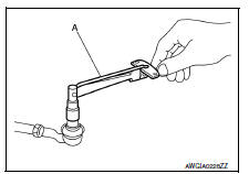
Ball joint rotating torque
-
Make sure that the reading is within the following specified range using Tool. Replace outer socket if the reading is outside the specification.
Tool number (A) : ST3127S000 (J-25765-A)
Rotating torque : Refer to ST-19, "Power Steering Gear".
INSPECTION AFTER INSTALLATION
-
Check if steering wheel turns smoothly when it is turned several times fully to the end of the left and right.
-
Check the steering wheel play, neutral position steering wheel, steering wheel turning force, and front wheel turning angle.
-
Steering wheel play: Refer to ST-5, "Inspection".
-
Neutral position steering wheel, steering wheel turning force, and front wheel turning angle: Refer to ST-5, "Inspection".
 Steering column
Inspection
STEERING COLUMN ASSEMBLY
Check each part of steering column assembly for damage or
other malfunctions. Replace entire steering column
assembly if any parts are damaged.
Me ...
 Symptom diagnosis
Noise, vibration and harshness (NVH) troubleshooting
NVH Troubleshooting Chart
Use the chart below to find the cause of the symptom. If
necessary, repair or replace these parts.
×: Appl ...
Other materials:
Sun visors
To block glare from the front, swing down the
sun visor.
To block glare from the side, remove the sun
visor from the center mount and swing the
visor to the side.
Slide the extension sun visor in or out as
needed.
CAUTION
Do not store the sun visor before returning
the exte ...
Preparation
Special Service Tools
The actual shape of the tools may differ from those illustrated here.
Commercial Service Tools
...
Interior trunk lid release
WARNINGClosely supervise children when they are
around cars to prevent them from playing
and becoming locked in the trunk where
they could be seriously injured. Keep the
car locked, with the rear seatback and
trunk lid securely latched when not in use,
and prevent childr ...
