Nissan Sentra Service Manual: Tcm branch line circuit
Diagnosis procedure
1.Check connector
- Turn the ignition switch off.
- Disconnect the battery cable from the negative terminal.
- Check the following terminals and connectors for damage, bend and loose connection (unit side and connector side).
- TCM
- Harness connector F50
- Harness connector e64
Is the inspection result normal? Yes >> go to 2.
No >> repair the terminal and connector.
2.Check harness for open circuit
- Disconnect the connector of tcm.
- Check the resistance between the tcm harness connector terminals.
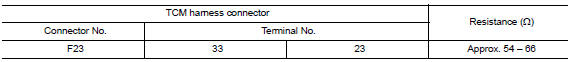
Is the measurement value within the specification? Yes >> go to 3.
No >> repair the tcm branch line.
3.Check power supply and ground circuit
Check the power supply and the ground circuit of the tcm. Refer to tm-234, "diagnosis procedure".
Is the inspection result normal? Yes (present error)>>replace the tcm. Refer to the tm-263, "removal and installation".
Yes (past error)>>error was detected in the tcm branch line.
No >> repair the power supply and the ground circuit.
 Ipdm-e branch line circuit
Diagnosis procedure
1.Check connector
Turn the ignition switch off.
Disconnect the battery cable from the negative terminal.
Check the terminals and connectors of the ipdm e/r for damage, ben ...
 A-bag branch line circuit
Diagnosis procedure
Warning:
Always observe the following items for preventing accidental
activation.
Before servicing, turn ignition switch off, disconnect battery
negative terminal, and w ...
Other materials:
NISSAN Intelligent Key® (if so equipped)
Replace the battery in the Intelligent Key as follows:
Remove the mechanical key from the Intelligent
Key.
Insert a small screwdriver A into the slit B
of the corner and twist it to separate the
upper part from the lower part. Use a cloth to
protect the casing.
Replace the battery wi ...
Brake master cylinder
Exploded View
Reservoir cap
Oil strainer
Reservoir tank
Cylinder body
Pin
O-ring
Grommet
Apply brake fluid
PBC (Poly Butyl Cuprysil)
grease or
silicone-based grease
Removal and Installation
REMOVAL
CAUTION:
Do not spill or splash brake fluid on painted surfaces. ...
P0112, P0113 IAT Sensor
DTC Logic
DTC DETECTION LOGIC
DTC No.
CONSULT screen terms
(Trouble diagnosis content)
DTC detecting condition
Possible cause
P0112
IAT SEN/CIRCUIT- B1
(Intake air temperature
sensor 1 circuit low bank 1)
An excessively low voltage from the intake air
tem ...
