Nissan Sentra B18 (2020-2025) Service Manual: System
Meter System
System Description
System Description
SYSTEM DIAGRAM
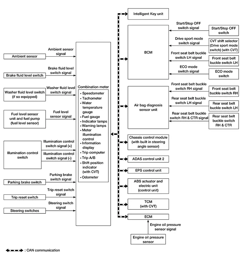
Combination Meter Input Signal (CAN Communication Signal)
|
Transmit unit |
Signal name |
|---|---|
|
ABS actuator and electric unit (control unit) |
Odometer signal |
|
ABS warning lamp signal |
|
|
VDC warning lamp signal |
|
|
VDC OFF indicator lamp signal |
|
|
Brake warning lamp signal |
|
|
Intelligent Key unit |
Buzzer output signal |
|
Meter display signal |
|
|
BCM |
Position light status signal |
|
Door switch signal |
|
|
High beam status signal |
|
|
Light reminder warning signal |
|
|
Turn indicator signal |
|
|
Meter display signal |
|
|
Sleep wake up signal |
|
|
Front seat belt buckle switch LH signal |
|
|
TPMS malfunction warning lamp signal |
|
|
Low tire pressure warning lamp signal |
|
|
Low tire pressure wheel location signal |
|
|
Dimmer signal |
|
|
ECO mode indicator lamp signal |
|
|
Buzzer output signal |
|
|
TCM (with CVT) |
Shift position signal |
|
Shift position indicator signal |
|
|
CVT warning message signal |
|
|
Ds mode indicator signal |
|
|
ECM |
Nissan Sentra Vehicle speed display signal |
|
Engine speed signal |
|
|
Engine coolant temperature signal |
|
|
Engine warning display signal |
|
|
Fuel filler cap warning display signal |
|
|
Fuel consumption monitor signal |
|
|
Remaining distance signal |
|
|
Malfunctioning indicator lamp signal |
|
|
Engine oil pressure warning lamp signal |
|
|
Engine status signal |
|
|
ECO mode indicator lamp signal |
|
|
ECO drive indicator control signal |
|
|
ECO pedal guide signal |
|
|
Battery warning request signal |
|
|
Stop/Start indicator lamp and message request signal |
|
|
EPS (Electric Power Steering) control unit |
EPS warning lamp signal |
|
ADAS control unit 2 |
AEB warning lamp signal |
|
RAB warning lamp signal |
|
|
Meter display signal |
|
|
Front camera unit |
Meter display signal |
|
Side radar LH |
Meter display signal |
|
Side radar RH |
Meter display signal |
|
Sonar control unit |
Parking sensor error signal |
|
Sonar indicator signal |
|
|
Air bag diagnosis sensor unit |
Front seat belt buckle switch RH signal |
|
Rear seat belt buckle switch LH signal |
|
|
Rear seat belt buckle switch RH signal |
|
|
Rear seat belt buckle switch center signal |
|
|
SRS air bag warning lamp signal |
|
|
IPDM E/R (Intelligent Power Distribution Module Engine Room) |
Headlamp warning signal |
|
Starter relay status signal |
|
|
Battery warning request signal |
|
|
Chassis control module (with built in steering angle sensor) |
Meter display signal |
DESCRIPTION
Combination Meter
-
The combination meter receives necessary signals from each unit, switch, and sensor to control the following functions:
-
Measuring instruments
-
Speedometer
-
Tachometer
-
Engine coolant temperature gauge
-
Fuel gauge
-
-
Warning lamps
-
Indicator lamps
-
Meter illumination control
-
Meter effect function
-
Information display
-
-
The combination meter incorporates a buzzer function that sounds an audible alarm with the integrated buzzer. For further details. Refer to System Description for further details.
-
The combination meter includes an on board diagnosis function.
-
The combination meter can be diagnosed with CONSULT.
METER CONTROL FUNCTION LIST
|
System |
Description |
Reference |
|||
|---|---|---|---|---|---|
|
Measuring instruments |
Speedometer |
Indicates Nissan Sentra vehicle speed. |
System Description |
||
|
Tachometer |
Indicates engine speed. |
System Description |
|||
|
Engine coolant temperature gauge |
Indicates engine coolant temperature. |
System Description |
|||
|
Fuel gauge |
Indicates fuel level. |
System Description |
|||
|
Warning lamp/indicator lamp |
Engine oil pressure warning lamp |
The warning lamp turns ON or turns OFF, according to engine hydraulic pressure. |
System Description |
||
|
Meter illumination control |
Meter illumination control function |
Switch back and forth between daytime mode and night mode, according to a light switch position. |
System Description |
||
|
Back light illumination control function |
The operation of the illumination control switch allows the brightness adjustment of meter illumination. |
||||
|
Meter effect function |
Engine-start effect function |
Meter illumination at ignition switch ON from OFF to produce illumination effects. |
System Description |
||
|
Information display |
The Information display displays status, according to system malfunction or Nissan Sentra vehicle condition. |
System Description |
|||
Speedometer
System Description
System Description
SYSTEM DIAGRAM
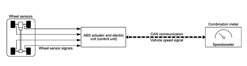
System Description
The ABS actuator and electric unit (control unit) receives each wheel speed sensor signal and provides a Nissan Sentra vehicle speed signal to the combination meter via CAN communication.
Tachometer
System Description
System Description
SYSTEM DIAGRAM
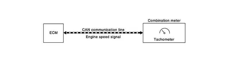
System Description
DESCRIPTION
The crank position sensor sends a crankshaft position signal to the ECM. The ECM provides an engine speed signal to the combination meter via CAN communication lines.
The tachometer indicates engine speed in revolutions per minute (rpm).
Engine Coolant Temperature Gauge
System Description
System Description
SYSTEM DIAGRAM
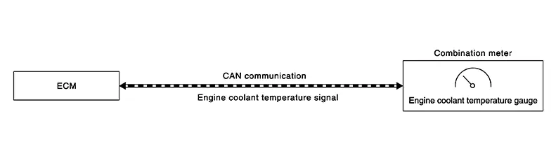
System Description
The engine coolant temperature sensor sends an engine coolant temperature signal to the ECM. The ECM provides an engine coolant temperature signal to the combination meter via CAN communication lines.
The engine coolant temperature gauge indicates the engine coolant temperature.
Fuel Gauge
System Description
System Description
SYSTEM DIAGRAM
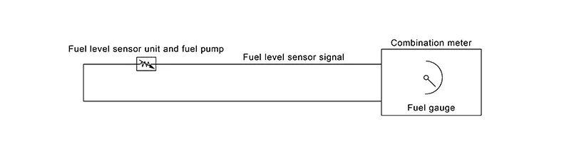
DESCRIPTION
Control Outline
The combination meter reads the fuel level sensor signal from the fuel level sensor unit and indicates the fuel level to the fuel gauge.
Refuel Control
The combination meter accelerates the fuel gauge if the all conditions listed below are met, or the ignition switch is ON from OFF.
-
Ignition switch is ON.
-
The Nissan Sentra vehicle is not moving.
-
The fuel level change by 4
 (1.05US gallons) or more.
Oil Pressure Warning Lamp
System Description
System Description
SYSTEM DIAGRAM
SYSTEM DIAGRAM
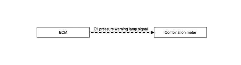
System Description
DESCRIPTION
The combination meter turns the oil pressure warning lamp ON when receiving a signal from the ECM via CAN communication.
Meter Illumination Control
System Description
System Description
SYSTEM DIAGRAM
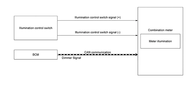
DESCRIPTION
Back Light Illumination Control Function
The operation of the illumination control switch allows the brightness adjustment of meter illumination.
|
Meter illumination |
The number of adjustable steps |
|---|---|
|
Daytime |
22 steps |
|
Nighttime |
22 steps |
Meter Illumination Control Function
-
Combination meter controls meter illumination, based on the dimmer signal.
-
When ignition is on the combination meter switches mode between Daytime mode and Nighttime mode, according to the following conditions.
Condition
Meter illumination
Combination switch
(lighting switch)
1ST or 2ND position
Outdoor: Bright*
Daytime mode
Outdoor: Dark*
Nighttime mode
AUTO POSITION
Outdoor: Bright*
Daytime mode
Outdoor: Dark*
Nighttime mode
Off
Daytime mode
*: For further information, refer to System Description.
Signal Path
|
Signal name |
Signal path |
|---|---|
|
Ignition signal |
ŌĆö |
|
Dimmer signal |
BCM |
Information Display
System Description
System Description
SYSTEM DIAGRAM
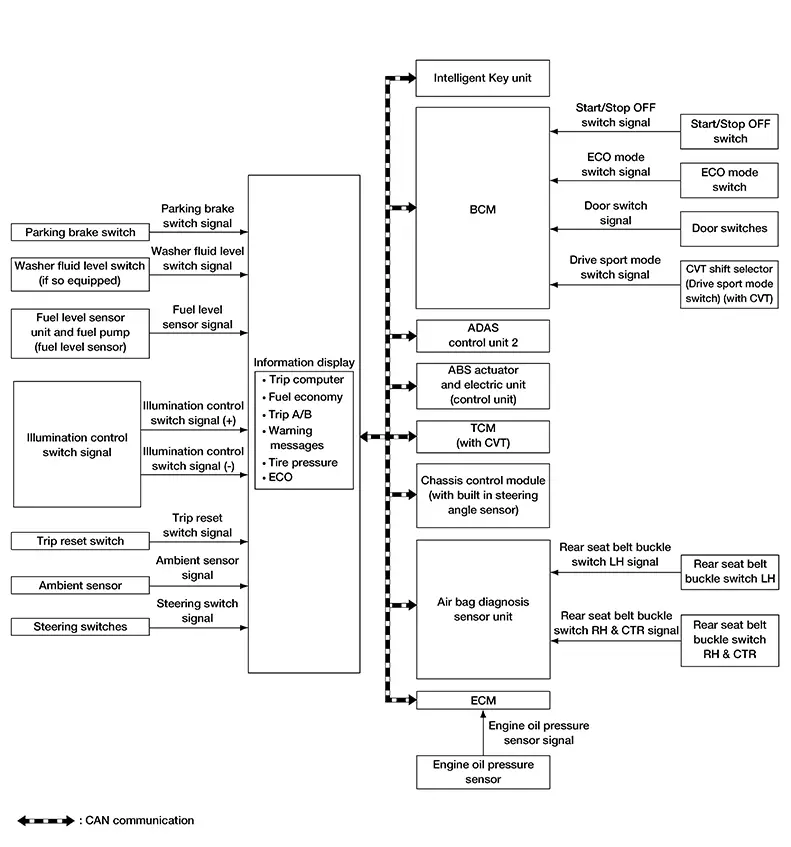
DESCRIPTION
-
The combination meter receives signals necessary for controlling the operation of the information display from each unit, sensor and switch.
-
The combination meter incorporates a trip computer that displays the warning/information according to the information received from each unit, sensor and switch.
-
The combination meter shows the following functions on the information display:
-
Warning/Indicator
-
Odo/trip meter
-
Distance to empty
-
Warning confirmation
-
Setting
-
Trip computer
-
Ambient temperature
-
Clock
-
Meter illumination level
-
ODO/TRIP METER
The combination meter calculates mileage, based on the following signals and displays the mileage on the information display.
|
Signal name |
Signal path |
|---|---|
|
Ignition signal |
ŌĆö |
|
Odometer signal |
ABS actuator and electric unit
(control unit) |
DISTANCE TO EMPTY
The combination meter calculates distance to empty based on the following signals, and the calculated value is displayed on the information display.
|
Signal name |
Signal source |
|---|---|
|
Ignition signal |
ŌĆö |
|
Fuel level sensor signal |
Fuel level sensor unit |
|
Fuel consumption monitor signal |
ECM |
|
Nissan Sentra Vehicle speed display signal |
ECM |
 Combination meter
-
Distance to empty on the information display is updated approximately every 30 seconds.
-
When at ignition switch ON right after battery removal and installation, ŌĆ£ŌłÆŌłÆŌłÆŌĆØ is displayed until after a travel of 30 seconds.
-
The indicated values may not match each other when refueling with the ignition switch ON.
WARNING CONFIRMATION
-
The combination meter can cause an interrupt on the information display to indicate a warning, based on signals received from each unit and switch.
-
The indicated warning can be checked with ŌĆ£WARNINGŌĆØ during the satisfaction of an interrupt indication condition for each warning.
SETTINGS
The condition of following items can be set:
-
VDC Setting
-
Driver Assistance
-
ECO Mode Setting
-
TPMS Setting
-
Clock
-
Nissan Sentra Vehicle Settings
-
Maintenance
-
Customize Display
-
Unit
-
Language
-
Factory Reset
TRIP COMPUTER
Current Fuel Consumption
The combination meter calculates current fuel consumption based on the following signals, and the calculated value is displayed on the information display.
Current fuel consumption can be compared with average fuel consumption.
|
Signal name |
Signal source |
|---|---|
|
Ignition signal |
ŌĆö |
|
Fuel consumption monitor signal |
ECM |
|
Nissan Sentra Vehicle speed display signal |
ECM |
|
Steering switch signal |
Steering switch |
-
Current fuel consumption on the information display is updated approximately every 0.1 seconds.
-
Current fuel consumption on the information display shows 0 mpg (0 l/100km) when Nissan Sentra vehicle speed is 0 MPH (0 km/h).
Average Fuel Consumption
The combination meter calculates average fuel consumption based on the following signals, and the calculated value is displayed on the information display.
|
Signal name |
Signal source |
|---|---|
|
Ignition signal |
ŌĆö |
|
Fuel consumption monitor signal |
ECM |
|
Nissan Sentra Vehicle speed display signal |
ECM |
|
Steering switch signal |
Steering switch |
-
Average fuel consumption on the information display is updated approximately every 30 seconds.
-
Soon after a reset or at ignition switch ON right after battery removal and installation, ŌĆ£ŌłÆŌłÆŌłÆŌĆØ is displayed until after a travel of 30 seconds and approximately 500 m (0.31 mile).
Current Nissan Sentra Vehicle Speed
The combination meter calculates current vehicle speed based on the following signals, and the calculated value is displayed on the information display.
|
Signal name |
Signal path |
|---|---|
|
Ignition signal |
ŌĆö |
|
Nissan Sentra Vehicle speed display signal |
ECM |
Current Nissan Sentra vehicle speed on the information display is updated approximately every 0.3 seconds.
Average Vehicle Speed
The combination meter calculates average Nissan Sentra vehicle speed based on the following signals, and the calculated value is displayed on the information display.
|
Signal name |
Signal source |
|---|---|
|
Ignition signal |
ŌĆö |
|
Nissan Sentra Vehicle speed display signal |
ECM |
|
Steering switch signal |
Steering switch |
-
Average fuel consumption on the information display is updated approximately every 30 seconds.
-
Soon after a reset or at ignition switch ON right after battery removal and installation, ŌĆ£ŌłÆŌłÆŌłÆŌĆØ is displayed until after a travel of 30 seconds and approximately 500 m (0.31 mile).
Travel Time
The combination meter measures and displays travel time (ignition switch ON time).
Travel Distance
The combination meter measures and displays travel distance.
ECO Drive Report
-
The ECO drive report is a function which displays
 ECO evaluation,
 the last five data of average fuel consumption,
  present fuel economy (present value),
and
present fuel economy (present value),
and  the best fuel economy (highest value)
on the information display by calculating and recording average fuel
consumption.
the best fuel economy (highest value)
on the information display by calculating and recording average fuel
consumption.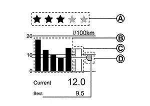
-
The combination meter calculates the average fuel consumption according to the signal below, detects the status of ECO mode , and displays ŌĆ£ECO drive reportŌĆØ on the information display at ignition switch ON from OFF.
Note:
ECO evaluation is displayed only when travelling ten minutes or more in ECO mode.
Signal name
Signal path
Ignition signal
ŌĆö
Fuel consumption monitor signal
ECM
 Combination meter
Nissan Sentra Vehicle speed display signal
ECM
Combination meterECO mode indicator signal
ECM
Combination meter
METER ILLUMINATION LEVEL
The combination meter displays the illuminance level of the back light on the information display by pressing the illumination control switch. Refer to System Description.
CLOCK
The combination meter calculates time and displays it on the information display.
Note:
The settings screen of the information display allows the selection of time indication between 12-hour and 24-hour formats.
AMBIENT TEMPERATURE
The combination meter calculates ambient temperature based on the following signals, and the calculated value is displayed on the information display.
|
Signal name |
Signal path |
|---|---|
|
Ignition signal |
ŌĆö |
|
Ambient sensor signal |
Ambient sensor |
|
Nissan Sentra Vehicle speed display signal |
ECM |
-
The indicated temperature is corrected based on an ignition signal, ambient temperature detected by the ambient sensor, and Nissan Sentra vehicle speed signal. The indicated temperature is not raised under vehicle speed less than 12 MPH (20 km/h).
-
The ambient sensor input value that is displayed on ŌĆ£Data MonitorŌĆØ of CONSULT is the value before the correction. It may not match the indicated temperature on the information display.
-
Depending on engine heat or heat on the road surfaces, an ambient temperature may be indicated higher than actual one.
Meter Effect Function
System Description
System Description
SYSTEM DIAGRAM
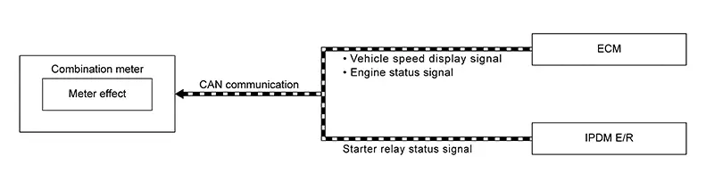
DESCRIPTION
Engine-start Effect Function
When recognizing an engine start, the combination meter controls the following items for producing the effect:
-
Speedometer
-
Tachometer
-
Information display
-
Meter illumination
Meter and Illumination Operations During Engine-start Effect
The combination meter controls the following items during the engine-start effect:
|
Control item |
Operation |
|
|---|---|---|
|
Speedometer |
Sweeps the pointer. |
|
|
Tachometer |
Sweeps the pointer. |
|
|
Illumination ring |
Increases the brightness to the effect level in stages. |
|
|
Pointers |
Turns on the illumination at the effect level. |
|
|
Information display |
Display the animation. |
|
The pointers are stopped and illumination is turned off while cranking the engine.
Engine Start Judgement
The combination meter judges ŌĆ£engine-startŌĆØ and activates the engine-start effect only once when the following operational conditions are all satisfied:
|
Operational condition |
|
|---|---|
|
Ignition switch |
ON position |
|
Nissan Sentra Vehicle speed |
Less than 0.6 mph (1 km/h) |
|
Engine state |
After cranking the engine |
|
Setting |
The setting of ŌĆ£Display EffectŌĆØ is ŌĆ£OnŌĆØ |
The engine-start effect exits when any of the above operational conditions is cancelled during the engine-start effect.
Signal Path
The combination meter judges ŌĆ£engine-startŌĆØ, according to the following signals and activates the engine-start effect function:
|
Signal name |
Signal source |
|---|---|
|
Ignition signal |
ŌĆö |
|
Engine status signal |
ECM |
|
Nissan Sentra Vehicle speed display signal |
ECM |
|
Starter relay status signal |
IPDM E/R |
The engine-start effect function ends if any one of the above conditions is lost during the activation of this function.
Other materials:
Cushion Heater Lh
Component Function Check
Component Function
Check
CHECK FUNCTION
Check that cushion heater LH warms to the preset
temperature when operating the heated seat switch LH to HIGH and LOW.
Is the inspection result normal?
...
Front Bumper
Exploded View
Exploded View
1.
Front bumper side bracket (RH)
2.
Front bumper reinforcement support
(RH)
...
B20c7-15 A/c Clutch
Dtc Description
DTC Description
DTC DETECTION LOGIC
DTC No.
CONSULT screen terms
(Trouble diagnosis content)
DTC detection condition
...