Nissan Sentra B18 (2020-2025) Service Manual: Component Parts
Meter System
Component Parts Location
Component Parts Location
MODELS WITH CVT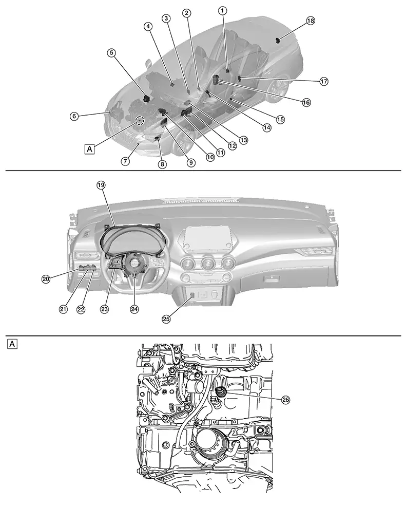
|
A. |
View of engine assembly removed |
|
No. |
Component |
Function |
|---|---|---|
|
1. |
Rear seat belt buckle switch RH & CTR |
Transmits the rear seat belt buckle switch RH & CTR signal to the air bag diagnosis sensor unit. |
|
2. |
Front seat belt buckle switch RH |
Transmits the front seat belt buckle switch RH signal to the air bag diagnosis sensor unit. |
|
3. |
CVT selector (drive sport mode switch) (if so equipped) |
Transmits the drive sport mode switch signal to the BCM. |
|
4. |
ADAS (Advanced Driver Assistance System) control unit 2 |
Transmits each signal to the combination meter via CAN communication. Refer to System Description. Refer to Component Parts Location for detailed component location. |
|
5. |
ABS (Anti-lock Braking System) actuator and electric unit (control unit) |
Transmits each signal to the combination meter via CAN communication. Refer to System Description. Refer to Component Parts Location for detailed component location. |
|
6. |
Washer fluid level switch (if so equipped) |
Transmits the washer fluid level switch signal to the combination meter. Refer to Component Parts Location for detailed component location. |
|
7. |
Ambient sensor |
Transmits the ambient sensor signal to the combination meter. |
|
8. |
TCM (Transmission Control Module) |
Transmits each signal to the combination meter via CAN communication. Refer to System Description. Refer to Component Parts Location for detailed component location. |
|
9. |
ECM (Engine Control Module) |
Transmits each signal to the combination meter via CAN communication. Refer to System Description. Refer to Component Parts Location for detailed component location. |
|
10. |
Brake fluid level switch |
Transmits the brake fluid level switch signal to the combination meter. Refer to Component Parts Location for detailed component location. |
|
11. |
Parking brake switch |
Transmits the parking brake switch signal to the combination meter. |
|
12. |
BCM (Body Control Module) |
Transmits each signal to the combination meter via CAN communication. Refer to System Description. Refer to Component Parts Location for detailed component location. |
|
13. |
Air bag diagnosis sensor unit |
Transmits each signal to the combination meter via CAN communication. Refer to System Description. Refer to Component Parts Location for detailed component location. |
|
14. |
Front seat belt buckle switch LH |
Transmits the front seat belt buckle switch LH signal to the BCM. |
|
15. |
Front door switch LH |
Transmits the front door switch LH signal to the BCM. |
|
16. |
Fuel level sensor unit and fuel pump (fuel level sensor) |
Transmits the fuel level sensor signal to the combination meter. |
|
17. |
Rear seat belt buckle switch LH |
Transmits the rear seat belt buckle switch LH signal to the air bag diagnosis sensor unit. |
|
18. |
Trunk lid opener assembly (ajar switch) |
Transmits the trunk lid opener assembly (ajar switch) signal to the BCM. |
|
19. |
Combination meter |
Refer to Combination Meter. |
|
20. |
ECO mode switch |
Transmits the ECO mode switch signal to the BCM. |
|
21. |
Illumination control switch |
Refer to Illumination Control Switch. |
|
22. |
Trip reset switch |
Refer to Trip Reset Switch. |
|
23. |
Steering switches |
Refer to Steering Switches. |
|
24. |
Combination switch (spiral cable) |
Provides a pass-through for the steering switch signal from the steering switches to the combination meter. |
|
25. |
Start/stop OFF switch (if so equipped) |
Transmits the start/stop OFF switch signal to the BCM. |
|
26. |
Engine oil pressure sensor |
Transmits the engine oil pressure sensor signal to the ECM. |

|
A. |
View of engine assembly removed |
|
No. |
Component |
Function |
|---|---|---|
|
1. |
Rear seat belt buckle switch RH & CTR |
Transmits the rear seat belt buckle switch RH & CTR signal to the air bag diagnosis sensor unit. |
|
2. |
Front seat belt buckle switch RH |
Transmits the front seat belt buckle switch RH signal to the air bag diagnosis sensor unit. |
|
3. |
ADAS (Advanced Driver Assistance System) control unit 2 |
Transmits each signal to the combination meter via CAN communication. Refer to System Description. Refer to Component Parts Location for detailed component location. |
|
4. |
ABS (Anti-lock Braking System) actuator and electric unit (control unit) |
Transmits each signal to the combination meter via CAN communication. Refer to System Description. Refer to Component Parts Location for detailed component location. |
|
5. |
Washer fluid level switch (if so equipped) |
Transmits the washer fluid level switch signal to the combination meter. Refer to Component Parts Location for detailed component location. |
|
6. |
Ambient sensor |
Transmits the ambient sensor signal to the combination meter. |
|
7. |
ECM (Engine Control Module) |
Transmits each signal to the combination meter via CAN communication. Refer to System Description. Refer to Component Parts Location for detailed component location. |
|
8. |
Brake fluid level switch |
Transmits the brake fluid level switch signal to the combination meter. Refer to Component Parts Location for detailed component location. |
|
9. |
BCM (Body Control Module) |
Transmits each signal to the combination meter via CAN communication. Refer to System Description. Refer to Component Parts Location for detailed component location. |
|
10. |
Air bag diagnosis sensor unit |
Transmits each signal to the combination meter via CAN communication. Refer to System Description. Refer to Component Parts Location for detailed component location. |
|
11. |
Parking brake switch |
Transmits the parking brake switch signal to the combination meter. |
|
12. |
Front seat belt buckle switch LH |
Transmits the front seat belt buckle switch LH signal to the BCM. |
|
13. |
Front door switch LH |
Transmits the front door switch LH signal to the BCM. |
|
14. |
Fuel level sensor unit and fuel pump (fuel level sensor) |
Transmits the fuel level sensor signal to the combination meter. |
|
15. |
Rear seat belt buckle switch LH |
Transmits the rear seat belt buckle switch LH signal to the air bag diagnosis sensor unit. |
|
16. |
Trunk lid opener assembly (ajar switch) |
Transmits the trunk lid opener assembly (ajar switch) signal to the BCM. |
|
17. |
Combination meter |
Refer to Combination Meter. |
|
18. |
ECO mode switch |
Transmits the ECO mode switch signal to the BCM. |
|
19. |
Illumination control switch |
Refer to Illumination Control Switch. |
|
20. |
Trip reset switch |
Refer to Trip Reset Switch. |
|
21. |
Steering switches |
Refer to Steering Switches. |
|
22. |
Combination switch (spiral cable) |
Provides a pass-through for the steering switch signal from the steering switches to the combination meter. |
|
23. |
Engine oil pressure sensor |
Transmits the engine oil pressure sensor signal to the ECM. |
Design
Design
ARRANGEMENT OF COMBINATION METER

|
A. |
USA |
B. |
Except USA |
Combination Meter
Combination Meter
The combination meter controls the following items according to the signals received from each unit via CAN communication and the signals from switches and sensors:
-
Measuring instruments
-
Indicator lamps
-
Warning lamps
-
Meter illumination control
-
Information display
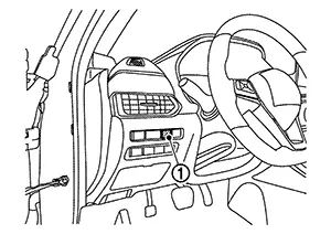
Trip Reset Switch
Trip Reset Switch
-
The trip reset switch is located on the instrument panel lower LH.
-
Transmits the trip reset signal to the combination meter.
|
No. |
Switch name |
Operation |
Description |
|---|---|---|---|
|
1. |
Trip reset switch |
Press |
|
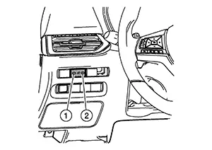
Illumination Control Switch
Illumination Control Switch
-
The illumination control switch is located on the instrument lower panel LH.
-
Transmits the following signals to the combination meter:
-
Illumination control switch signal (+)
-
Illumination control switch signal (−)
-
|
No. |
Switch name |
Operation |
Description |
|---|---|---|---|
|
1. |
Illumination control switch (−) |
Press |
The brightness of combination meter and information display can be adjusted. |
|
2. |
Illumination control switch (+) |
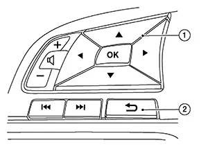
Steering Switches
Steering Switches
-
The steering switches are located on the steering wheel.
-
The steering switch transmits the steering switch signal to the combination meter.
|
No. |
Switch name |
Operation |
Description |
|---|---|---|---|
|
1. |
OK/Up/Down/Left/Right switch |
Press |
The information display settings can be changed. |
|
2. |
Back switch |
Other materials:
Heated Seat Lh Relay
Component Function Check
Component Function
Check
CHECK HEATED SEAT LH RELAY FUNCTION
Check that seat cushion and seat back warm to the
preset temperature when operating the heated seat switch LH to HIGH
and LOW.
...
Squeak and Rattle Trouble Diagnoses
Work Flow
Work Flow
CUSTOMER INTERVIEW
Interview the customer if possible, to determine
the conditions that exist when the noise occurs. Use the Diagnostic
Worksheet during the interview to document the facts and conditions
when the noise occurs and any customer's comments; refer ...
Basic Inspection
Diagnosis and Repair Work Flow
Work Flow
Work Flow
OVERALL SEQUENCE
DETAILED FLOW
INTERVIEW FOR MALFUNCTION
It is also important to clarify the customer
concerns before starting the inspection. Interview the
customer about the concerns carefully and ...