Nissan Sentra B18 (2020-2025) Service Manual: System
System Description
System Description
SYSTEM DIAGRAM
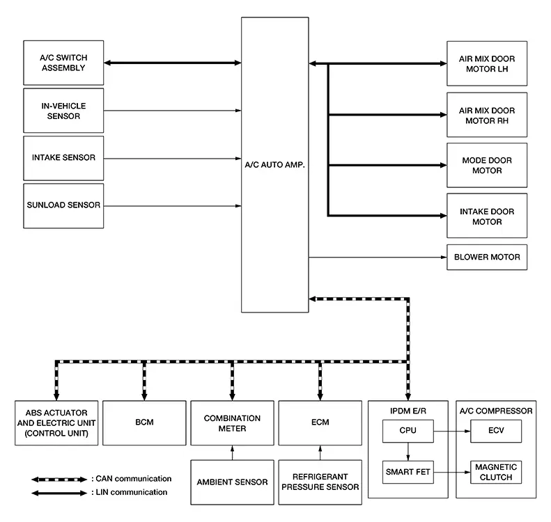
INPUT SIGNAL AND OUTPUT SIGNAL
|
Control unit |
Signal status |
|---|---|
|
ABS actuator and electric unit (control unit) |
Transmits the Nissan Sentra vehicle speed signal to A/C auto amp. via CAN communication. |
|
BCM |
Transmits the remote engine start status signal to A/C auto amp. via CAN communication. |
|
Combination meter |
|
|
ECM |
|
|
IPDM E/R |
The Smart FET is integrated in the IPDM E/R:
|
|
A/C switch assembly |
|
|
Air mix door motor LH |
|
|
Air mix door motor RH |
|
|
Mode door motor |
|
|
Intake door motor |
DESCRIPTION
-
Automatic air conditioning system is controlled by each function of A/C auto amp., ECM and IPDM E/R.
-
Each operation of air conditioning system can be controlled by the A/C switch assembly.
CONTROL BY A/C AUTO AMP.
-
Temperature Control: Refer to Temperature Control.
-
Air Outlet Control: Refer to Air Outlet Control.
-
Air Inlet Control: Refer to Air Inlet Control.
-
Door Control: Refer to Door Control.
-
Air Flow Control: Refer to Air Flow.
-
Compressor Control: Refer to Compressor Control.
-
Cooling Fan Operation Request Control: Refer to System Description.
-
ECO mode control: Refer to System Description.
CORRECTION FOR INPUT VALUE
-
Ambient temperature correction
-
A/C auto amp. inputs the temperature detected by ambient temperature signal received from combination meter via CAN communication as the ambient temperature.
-
A/C auto amp. performs the correction of the temperature detected by ambient sensor for air conditioning control.
-
A/C auto amp. selects and uses the initial value of ambient temperature data depending on the engine coolant temperature when placing the ignition switch from OFF to ON. The detection temperature of the ambient sensor is used when engine coolant temperature is low [less than approximately 133┬░F (56┬░C)]. The memory data (before the ignition switch is OFF) when the engine is warmed up [approximately 133┬░F (56┬░C) or more].
-
The correction of the ambient temperature is not performed when the detection temperature of the ambient temperature is less than approximately ŌłÆ4┬░F (ŌłÆ20┬░C).
-
-
In-Nissan Sentra vehicle temperature correction
-
A/C auto amp. inputs the temperature detected by in-vehicle sensor as the in-Nissan Sentra vehicle temperature.
-
A/C auto amp. performs the correction of the temperature detected by in-Nissan Sentra vehicle sensor for air conditioning control.
-
A/C auto amp. performs the correction so that the recognition passenger room temperature changes depending on the difference between the detected passenger room temperature and the recognition passenger room temperature. If the difference is large, the changing is early. The changing becomes slow as the difference becomes small.
-
-
Intake temperature correction
-
A/C auto amp. inputs the temperature detected by intake sensor as the intake temperature (evaporator temperature).
-
A/C auto amp. performs the correction of the temperature detected by intake sensor for air conditioning control.
-
A/C auto amp. performs the correction so that the recognition intake temperature changes depending on the difference between the detected intake temperature and the recognition intake temperature. If the difference is large, the changing is early. The changing becomes slow as the difference becomes small.
-
-
Sunload amount correction
-
A/C auto amp. inputs the sunload amount detected by sunload sensor.
-
A/C auto amp. performs the correction of the sunload amount detected by sunload sensor for air conditioning control.
-
When the sunload amount suddenly changes, for example when entering a tunnel, perform the correction so that the recognition sunload amount of the A/C auto amp. changes slowly.
-
-
Set temperature correction
-
A/C auto amp. performs the correction to the target temperature set by the temperature control dial so as to match the temperature felt by the passengers depending on the ambient temperature detected by ambient sensor and controls it so that the in-Nissan Sentra vehicle temperature is always the most suitable.
-
CONTROL BY ECM
Compressor control: Refer to System Description.
CONTROL BY IPDM E/R
Compressor control: Refer to System Description.
Air Flow Control
Air Flow Control
DESCRIPTION
-
A/C auto amp. changes duty ratio of blower motor drive signal and controls air flow continuously. When air flow is increased, duty ratio of blower motor control signal gradually increases to prevent a sudden increase in air flow.
-
In addition to manual control and automatic control, air flow control consists of starting fan speed control, low coolant temperature starting control, high in-Nissan Sentra vehicle temperature starting control and fan speed control at door motor operation.
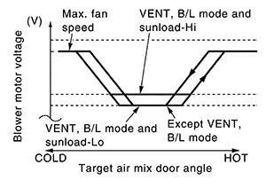
AUTOMATIC AIR FLOW CONTROL
-
A/C auto amp. decides target air flow depending on target air mix door opening angle.
-
A/C auto amp. changes duty ratio of blower motor control signal and controls the air flow continuously so that air flow matches the target air flow.
-
When air outlet is VENT or B/L, the minimum air flow is changed depending on sunload.
STARTING AIR FLOW CONTROL
-
When blower motor is activated, A/C auto amp. gradually increases duty ratio of blower motor control signal to prevent a sudden increase in discharge air flow.
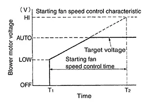
-
It takes approximately 8 seconds for air flow to reach HI from LOW.
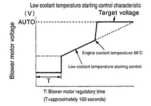
LOW COOLANT TEMPERATURE STARTING CONTROL
If the engine coolant temperature is 133┬░F (56┬░C) or less, to prevent a cold discharged air flow, A/C auto amp. suspends blower motor activation for a maximum of 150 seconds depending on target air mix door opening angle. After this, blower motor control signal is increased gradually, and blower motor is activated.
HIGH IN-Nissan Sentra Vehicle TEMPERATURE STARTING CONTROL
When front evaporator fin temperature is high [intake sensor value is 95┬░F (35┬░C) or more], to prevent a hot discharged air flow, A/C auto amp. suspends blower motor activation for approximately 3 seconds so that front evaporator is cooled by refrigerant.
FAN SPEED CONTROL AT DOOR MOTOR OPERATION
When mode door motor is activated while air flow is more than the specified value, A/C auto amp. reduces fan speed temporarily so that mode door moves smoothly.
Air Inlet Control
Air Inlet Control
The intake door is automatically controlled by the temperature setting, ambient temperature, in-vehicle temperature, intake temperature, amount of sunload and ON/OFF operation of the A/C compressor.
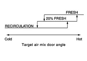
Intake door automatic control selects FRE, 20% FRE, or REC depending on a target air mix door opening angle, based on in-Nissan Sentra vehicle temperature, ambient temperature, and sunload.
Air Outlet Control
Air Outlet Control
-
While air outlet is in automatic control, A/C auto amp. selects the mode door position depending on a target air mix door angle and outlet air temperature calculated from sunload.
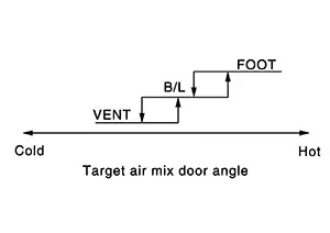
-
If ambient temperature is excessively low, D/F is selected to prevent windshield fogging when air outlet is set to FOOT.
Compressor Control
Compressor Control
DESCRIPTION
-
When the A/C compressor activation condition is satisfied while blower motor is activated, A/C auto amp. transmits A/C ON signal and blower fan ON signal to ECM via CAN communication line.
-
ECM judges the conditions of each sensor (Refrigerant pressure sensor signal, accelerator position signal, etc.), and transmits the A/C compressor request signal to IPDM E/R via CAN communication line.
-
By receiving the A/C compressor request signal from ECM, IPDM E/R turns the smart FET to ON, and activates the A/C compressor.
CONTROL BY A/C AUTO AMP.
Low Temperature Protection Control
When intake sensor detects that evaporator fin
temperature is  [23.0┬░F (ŌłÆ5.0┬░C) or less, A/C auto amp.
requests ECM to turn the A/C compressor OFF, and stops the A/C compressor.
[23.0┬░F (ŌłÆ5.0┬░C) or less, A/C auto amp.
requests ECM to turn the A/C compressor OFF, and stops the A/C compressor.
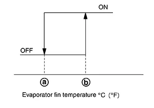
When the air temperature returns to  [33.8┬░F (1.0┬░C)] or more, the A/C
compressor
is activated.
[33.8┬░F (1.0┬░C)] or more, the A/C
compressor
is activated.
Refrigerant Discharge Amount Control
-
When setting temperature is full cold or air outlet is other than DEF, A/C auto amp. controls the refrigerant discharge amount by adjust the duty ratio of ECV according to required amount of cooling capacity.
-
When evaporator temperature is target temperature upper limit value or more, A/C auto amp. increases the discharge amount.
-
When evaporator temperature is less than target temperature upper limit value, A/C auto amp. reduces the discharge amount.

Target temperature upper limit value of evaporator can be changed using ŌĆ£TARGET EVAPORATOR TEMP UPPER LIMIT SETTINGŌĆØ in ŌĆ£Work supportŌĆØ mode of CONSULT.
Compressor Oil Circulation Control
When the engine starts, A/C auto amp. activates the A/C compressor for a few seconds and circulates the A/C compressor oil once.
CONTROL BY ECM
Compressor Protection Control at Pressure Malfunction
The high-pressure side value that is detected by refrigerant pressure sensor is excessively low or high, ECM requests IPDM E/R to turn smart FET OFF and stop the A/C compressor.
Air Conditioning Cut Control
When the engine condition is high load, ECM transmit smart FET OFF request to IPDM E/R, and stops the A/C compressor.
Door Control
Door Control
DOOR MOTOR CONTROL
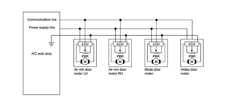
-
LCU (Local Control Unit) is built into each door motor, and detects door position by PBR (Potentio Balance Resistor).
-
A/C auto amp. communicates with each LCU via communication line and receives each door position feedback signal from each LCU.
-
Each LCU controls each door to the appropriate position depending on the control signal from A/C auto amp.
-
Each LCU transmits the signal of door movement completion to A/C auto amp., when the door movement is completed.
SWITCH AND THEIR CONTROL FUNCTION
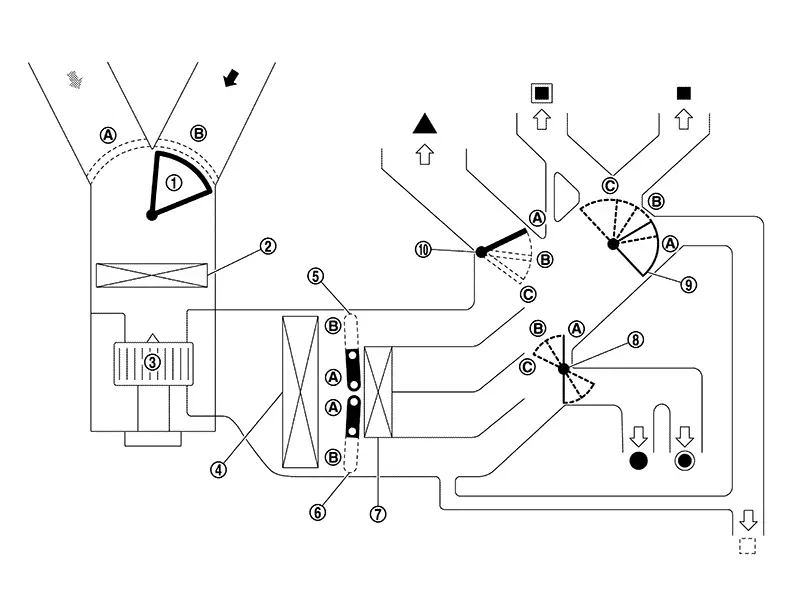
|
|
Intake door |
|
Air conditioner filter |
|
Blower motor |
|
|
Evaporator |
|
Upper air mix door (driver side/passenger side) |
|
Lower air mix door (driver side/passenger side) |
|
|
Heater core |
|
Foot door |
|
Ventilator door |
|
|
Defroster door |
||||
|
|
Fresh air |
|
Recirculation air |
|
Discharge air |
|
|
Defroster |
|
Center ventilator |
|
Side ventilator |
|
|
Front foot |
|
Rear foot* |
|
Rear ventilator* |


*: With rear ventilator
|
Switch position |
Door position |
||||||||
|---|---|---|---|---|---|---|---|---|---|
|
Mode door |
Intake door |
Air mix door (Driver side) |
Air mix door (Passenger side) |
||||||
|
Ventilator door |
Foot door |
Defroster door |
|||||||
|
AUTO switch |
|
AUTO |
ŌĆö |
ŌĆö |
ŌĆö |
||||
|
MODE switch |
|
|
|
|
|||||
|
|
|
|
|
||||||
|
|
|
|
( |
||||||
|
|
|
|
|
||||||
|
DEF switch |
|
|
|
|
|
||||
|
Intake switch1 |
REC |
|
|
ŌĆö |
ŌĆö |
ŌĆö |
|
||
|
FRE |
|
|
|||||||
|
Temperature control dial (Driver side) |
SYNC switch: ON |
Full cold 60┬░F or 61┬░F (18.0┬░C) |
ŌĆö |
|
|||||
|
62┬░F - 88┬░F (18.5┬░C ŌĆō 31.5┬░C) |
AUTO |
||||||||
|
Full hot 89┬░F or 90┬░F (32.0┬░C) |
|
||||||||
|
Temperature control dial (Driver side) |
SYNC switch: OFF |
Full cold 60┬░F or 61┬░F (18.0┬░C) |
|
ŌĆö |
|||||
|
62┬░F - 88┬░F (18.5┬░C ŌĆō 31.5┬░C) |
AUTO |
||||||||
|
Full hot 89┬░F or 90┬░F (32.0┬░C) |
|
||||||||
|
Temperature control dial (Passenger side) |
Full cold 60┬░F or 61┬░F (18.0┬░C) |
ŌĆö |
|
||||||
|
62┬░F - 88┬░F (18.5┬░C ŌĆō 31.5┬░C) |
AUTO |
||||||||
|
Full hot 89┬░F or 90┬░F (32.0┬░C) |
|
||||||||
|
ON┬ĘOFF switch |
OFF |
|
|
( |
ŌĆö |
||||


1: Air inlet status is displayed by indicator during activating automatic control
2: Default setting
3: It can be changed using ŌĆ£BLOW SETŌĆØ in ŌĆ£Work supportŌĆØ mode of CONSULT.
AIR DISTRIBUTION
|
Discharge air flow |
|||||||
|---|---|---|---|---|---|---|---|
|
MODE/DEF setting position |
Air outlet/distribution |
||||||
|
Ventilator |
Foot |
Defroster |
|||||
|
Front |
Rear |
Front |
Rear |
||||
|
Center |
Side |
||||||
|
|
43% |
43% |
14% |
ŌĆö |
ŌĆö |
ŌĆö |
|
|
|
24% |
24% |
10% |
32% |
10% |
ŌĆö |
|
|
|
ŌĆö |
10% |
10% |
45% |
15% |
20% |
|
|
|
ŌĆö |
10% |
10% |
30% |
15% |
35% |
|
|
|
ŌĆö |
14% |
12% |
ŌĆö |
ŌĆö |
74% |
|
Temperature Control
Temperature Control
-
When ignition switch is in the ON position, A/C auto amp. always automatically controls temperature regardless of front air conditioning operational state.
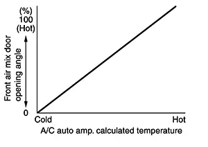
-
A/C auto amp. calculates the target air mix door opening angle depending on set temperature, in-Nissan Sentra vehicle temperature, ambient temperature, and sunload.
-
Air mix door is controlled depending on the comparison of current air mix door opening angle and target air mix door opening angle.
-
Regardless of in-Nissan Sentra vehicle temperature, ambient temperature, and sunload, air mix door is fixed at the fully cold position when set temperature is 60┬░F or 61┬░F (18.0┬░C), and at the fully hot position when set temperature is 89┬░F or 90┬░F (32.0┬░C).
Other materials:
Diagnosis System (bcm)
Common Item
Consult Function (bcm - Common Item)
CONSULT Function (BCM - COMMON ITEM)
BCM
Refer to CONSULT Function (BCM - COMMON ITEM).
Int Lamp
Consult Function (bcm - Int Lamp)
CON ...
B2f73-23 Clutch Switch
Dtc Description
DTC Description
DTC DETECTION LOGIC
DTC No.
CONSULT screen items
(Trouble diagnosis
content)
DTC detecting condition
...
Camera Aiming Adjustment
Work Procedure
Work Procedure
Always adjust the camera aiming after removing and
installing or replacing the front camera unit.
Always adjust the camera aiming after removing and
installing or replacing the windshield glass.
CAUTION:
...