Nissan Sentra B18 (2020-2025) Service Manual: Component Parts
Automatic Air Conditioner System
Component Parts Location
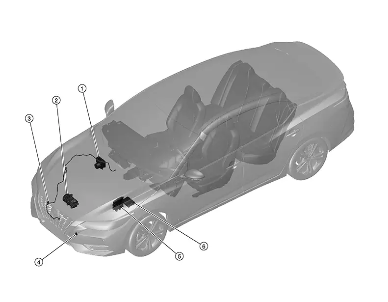
Component Parts Location
|
No. |
Component |
Function |
|
|---|---|---|---|
|
1. |
ABS (Anti-lock Brake System) actuator and electric unit (control unit) |
ABS actuator and electric unit (control unit) transmits Nissan Sentra vehicle speed signal to A/C auto amp. via CAN communication. Refer to Component Parts Location for detailed component location. |
|
|
2. |
A/C compressor |
Refer to A/C Compressor. |
|
|
3. |
Refrigerant pressure sensor |
Refer to Refrigerant Pressure Sensor. |
|
|
4. |
Ambient sensor |
Refer to Ambient Sensor. |
|
|
5. |
ECM (Engine Control Module) |
The ECM sends an A/C compressor ON request to the IPDM E/R based on the status of engine operation and load as well as refrigerant pressure information. If all the conditions are met for A/C operation, the ECM transmits the A/C compressor ON request to the IPDM E/R. The ECM shares the refrigerant pressure sensor signal, engine RPM, and engine coolant temperature with the A/C auto amp. via CAN communication line. Refer to Component Parts Location for detailed component location. |
|
|
6. |
IPDM E/R (Intelligent Power Distribution Module Engine Room) |
IPDM E/R operates smart FET (Field-Effect Transistor) when A/C compressor request signal is received from ECM via CAN communication line. Refer to System Description. |
|
|
No. |
Component |
Function |
|
|---|---|---|---|
|
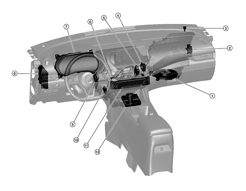
1. |
Blower motor |
Refer to Blower Motor. |
|
|
2. |
Intake door motor |
Refer to Intake Door Motor. |
|
|
3. |
Sunload sensor |
Refer to Sunload Sensor. |
|
|
4. |
Mode door motor |
Refer to Mode Door Motor. |
|
|
5. |
Air mix door motor RH |
Refer to Air Mix Door Motor RH. |
|
|
6. |
Intake sensor |
Refer to Intake Sensor. |
|
|
7. |
Combination Meter |
Combination meter transmits ambient temperature signal and ECO customize function signal to A/C auto amp. via CAN communication line. Refer to Combination Meter for detailed component location. |
|
|
8. |
BCM (Body Control Module) |
BCM transmits remote engine start status signal to A/C auto amp. via CAN communication. Refer to System Description. |
|
|
9. |
Air mix door motor LH |
Refer to Air Mix Door Motor LH. |
|
|
10. |
In-Nissan Sentra vehicle sensor |
Refer to In-Nissan Sentra Vehicle Sensor. |
|
|
11. |
A/C switch assembly |
A/C control operation signal is transmitted from the A/C switch assembly to the A/C auto amp. Refer to A/C Switch Assembly. |
|
|
12. |
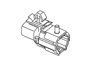
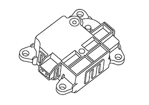
A/C auto amp. |
Refer to A/C Auto Amp.. |
|
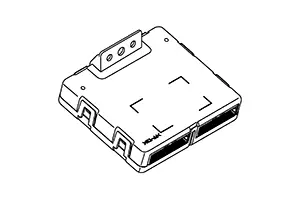
A/c Auto Amp.
A/C Auto Amp.
COMPONENT FUNCTION WITHIN SYSTEM
-
Located behind front side of center console.
-
A/C auto amp. controls the automatic air conditioning system by inputting and calculating signals from each sensor and each switch.
INDIVIDUAL COMPONENT FUNCTION
-
The A/C auto amp. consists of a microcomputer and input/output connectors for signals and power supply.
-
It has a CAN communications function, and it transmits and receives the necessary signals from each control module via CAN communication.
-
It has a LIN communications function, and transmits and receives signals to/from the A/C switch assembly and door motors.
-
A/C auto amp. has self-diagnosis function. Diagnosis of automatic air conditioning system can be performed quickly.
COMPONENT OPERATION
Refer to System Description.
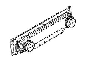
A/c Switch Assembly
A/C Switch Assembly
COMPONENT FUNCTION WITHIN SYSTEM
-
Located at center of instrument panel.
-
A/C switch assembly transmits setting status to A/C auto amp. via LIN communication line. A/C auto amp. controls automatic air conditioning system.
-
A/C switch assembly has switches and display that can set and indicate the operation of automatic air conditioning system.
INDIVIDUAL COMPONENT FUNCTION
-
The conditions that are set for the automatic air conditioning system that is operated by each control switch are transmitted to the A/C auto amp. via LIN communication.
-
The operating status of the automatic air conditioner is transmitted from the A/C auto amp. via LIN communication.
COMPONENT OPERATION
-
The operation status of each switch is detected by the control and is transmitted as an operation signal to the A/C auto amp. via LIN communication.
-
The following switch specification control was adopted:
-
Temperature control: Dial type
-
Air outlet control: Push-return type
-
Air inlet control: Push-return type
-
Air flow control: Push-return type
-
A/C compressor ON/OFF: Push-return type
Note:
Regarding the push switches : Refer to the following for the differences between push-lock types and push-return types.
Operation
Push-lock type
Push-return type
Switch ON operation
Switch OFF operation
Push-lock type
-
Switch ON operation: At the time of switch ON operation, the switch is pushed from the reference point
 to the pushed
position
to the pushed
position  , and the switch turns ON. When the switch
is released from this position, the switch returns from the pushed
position to the hold position
, and the switch turns ON. When the switch
is released from this position, the switch returns from the pushed
position to the hold position  , and the switch position is held there.
 -
Switch OFF operation: At the time of the switch OFF operation, the switch is pushed from the hold position
to
the pushed position . When the switch is released from this
position, the switch returns from the pushed position to the
reference point , and the switch turns OFF.
Push-return type
-
Switch ON operation: At the time of the switch ON operation, the switch is pushed from the reference point
to
the pushed position , and the switch turns ON. When the switch
is released from this position, the switch returns from the pushed
position to the reference point . -
Switch OFF operation: At the time of the switch OFF operation, the switch is pushed from the reference point
to the pushed position , and the switch turns OFF. When the
switch is released from this position, the switch returns from the
pushed position to the reference point .
-
-
-
For details the function of each switch. Refer to Switch Name and Function.
Ambient Sensor
Ambient Sensor
COMPONENT FUNCTION WITHIN SYSTEM
-
Located behind LH side of front bumper fascia.
-
The ambient sensor detects the temperature of the ambient air, and transmits the ambient sensor signal to the combination meter.
-
This signal is transmitted from the combination meter to the A/C auto amp. via CAN communication and is used in air conditioning system.
INDIVIDUAL COMPONENT FUNCTION
The ambient sensor measures the ambient air temperature.
COMPONENT OPERATION
The ambient sensor measures the ambient air temperature, and transmits the ambient sensor signal to the combination meter. This sensor uses a thermistor with electrical resistance that decreases as the temperature increases.

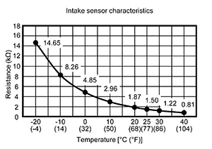
Intake Sensor
Intake Sensor
COMPONENT FUNCTION WITHIN SYSTEM
-
Located behind LH side of instrument panel.
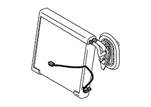
-
The intake sensor converts the evaporator surface temperature detected with thermistor into the voltage, and the A/C auto amp. inputs this voltage.
INDIVIDUAL COMPONENT FUNCTION
Intake sensor measures evaporator temperature (through air temperature).
COMPONENT OPERATION
The sensor uses a thermistor which is sensitive to the change in temperature. The electrical resistance of the thermistor decreases as temperature increases.
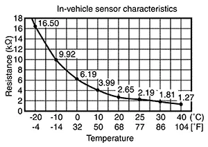
In-Vehicle Sensor
In-Vehicle Sensor
COMPONENT FUNCTION WITHIN SYSTEM
-
Located behind LH side of instrument panel.
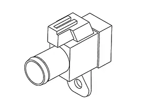
-
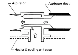
The in-Nissan Sentra vehicle sensor detects the temperature of the in-vehicle air that is taken in by the aspirator, and transmits the in-Nissan Sentra vehicle sensor signal to the A/C auto amp.
INDIVIDUAL COMPONENT FUNCTION
The in-Nissan Sentra vehicle sensor measures the temperature of the in-vehicle air taken in by the blower motor.
COMPONENT OPERATION
The in-Nissan Sentra vehicle sensor measures the temperature of the in-vehicle air that is taken in by the aspirator, and transmits the in-Nissan Sentra vehicle sensor signal to the A/C auto amp. This sensor uses a thermistor with electrical resistance that decreases as the temperature increases.
 Note:
Note:
The aspirator generates the vacuum by the air blown from the heater & cooling unit case and draws the air of the passenger room to the in-Nissan Sentra vehicle sensor area via the aspirator duct.
Refrigerant Pressure Sensor
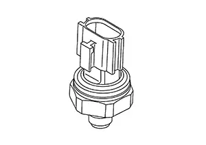
Refrigerant Pressure Sensor
COMPONENT FUNCTION WITHIN SYSTEM
-
Located at RH side of engine room.
-
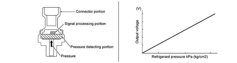
The refrigerant pressure sensor converts high-pressure side refrigerant pressure into voltage and outputs it to ECM.
-
This value is transmitted from the ECM to the A/C auto amp. via CAN communication and is used in compressor control and cooling fan operation request control.
INDIVIDUAL COMPONENT FUNCTION
The refrigerant pressure sensor converts refrigerant pressure into voltage.
COMPONENT OPERATION
-
The refrigerant pressure sensor is a capacitance type sensor. It consists of a pressure detection area and a signal processing area.
-
The pressure detection area, which is a variable capacity condenser, changes internal static capacitance according to pressure force.
-
The signal processing area detects the static capacitance of the pressure detection area, converts the static capacitance into a voltage value, and transmits the voltage value to ECM.
-
The output voltage increases as the refrigerant pressure rises.
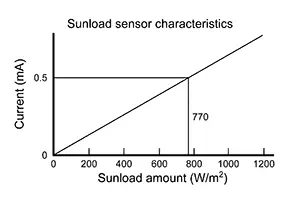
Sunload Sensor
Sunload Sensor
COMPONENT FUNCTION WITHIN SYSTEM
-
Located at right top of instrument panel.
-
Sunload sensor converts sunload amount to voltage signal by photodiode and transmits to A/C auto amp.
INDIVIDUAL COMPONENT FUNCTION
Sunload sensor measures sunload amount.
COMPONENT OPERATION
The sunload sensor measures the sunload and outputs the sunload sensor signal to the A/C auto amp. This sensor uses a photodiode with an electrical current that increases as the sunload increases.
Air Mix Door Motor Lh
Air Mix Door Motor LH
COMPONENT FUNCTION WITHIN SYSTEM
-
Located behind LH side of instrument panel.
-
Air mix door motor LH consists of motor that drives door, PBR (Potentio Balance Register) that detects door position and LCU (Local Control Unit) that perform multiplex communication control (LIN) with A/C auto amp.
INDIVIDUAL COMPONENT FUNCTION
Rotation of motor is transmitted to air mix door LH. Air flow temperature is switched.
Air Mix Door Motor Rh
Air Mix Door Motor RH
COMPONENT FUNCTION WITHIN SYSTEM
-
Located behind RH side of instrument panel.
-
Air mix door motor RH consists of motor that drives door, PBR (Potentio Balance Register) that detects door position and LCU (Local Control Unit) that perform multiplex communication control (LIN) with A/C auto amp.
INDIVIDUAL COMPONENT FUNCTION
Rotation of motor is transmitted to air mix door RH. Air flow temperature is switched.
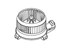
Blower Motor
Blower Motor
COMPONENT FUNCTION WITHIN SYSTEM
-
Located behind RH side of instrument panel.
-
The rotation speed is changed according to the voltage controlled by the A/C auto amp. and the air flow rate is controlled.
INDIVIDUAL COMPONENT FUNCTION
The motor with the sirocco fan rotates, taking in-Nissan Sentra vehicle or ambient air and sending it into the passenger room.
COMPONENT OPERATION
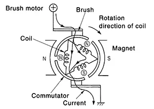
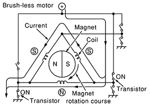
The blower motor adopts the brush motor.
Note:
-
Brush motor rotates the coil while the brush functions as contact point.
-
Brush-less motor, the magnet part rotates.
Intake Door Motor
Intake Door Motor
COMPONENT FUNCTION WITHIN SYSTEM
-
Located behind RH side of instrument panel.
-
Intake door motor consists of motor that drives door, PBR (Potentio Balance Register) that detects door position and LCU (Local Control Unit) that perform multiplex communication control (LIN) with A/C auto amp.
INDIVIDUAL COMPONENT FUNCTION
Rotation of motor is transmitted to intake door. Air inlet is switched.
Mode Door Motor
Mode Door Motor
COMPONENT FUNCTION WITHIN SYSTEM
-
Located behind RH side of instrument panel.
-
Mode door motor consists of motor that drives door, PBR (Potentio Balance Register) that detects door position and LCU (Local Control Unit) that perform multiplex communication control (LIN) with A/C auto amp.
INDIVIDUAL COMPONENT FUNCTION
Rotation of motor is transmitted to mode door (ventilator door, foot door, and defroster door). Air outlet is switched.
A/c Compressor
A/C Compressor
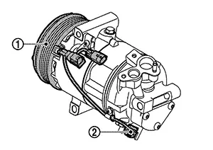
COMPONENT FUNCTION WITHIN SYSTEM
-
Located at lower RH side of engine compartment.
-
IPDM E/R controls the magnet clutch and ECV (electrical control valve) according to the requests from the A/C auto amp. and ECM, and changes the A/C compressor drive and refrigerant discharge amount.
INDIVIDUAL COMPONENT FUNCTION
For controlling the A/C compressor, a magnet clutch  that drives the A/C
compressor is used,
together with an ECV
that drives the A/C
compressor is used,
together with an ECV  that changes the refrigerant discharge
amount.
that changes the refrigerant discharge
amount.
Magnet Clutch
The magnet clutch turns ON/OFF, transmitting the rotational motion of the engine to the A/C compressor.
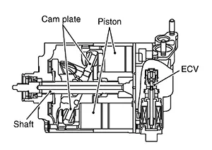
ECV (Electrical Control Valve)
Changing the cam plate angle, it changes the piston stroke and controls the refrigerant discharge amount.
COMPONENT OPERATION
Magnet Clutch
-
Magnet clutch consists of pulley, clutch disc, and field coil.
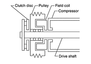
-
Pulley is connected with crankshaft pulley of engine via drive belt and is always rotated while engine is running.
-
Clutch disc is connected with drive shaft of A/C compressor.
-
Field coil, which becomes a strong electric magnet when electricity is supplied, strongly pulls clutch disc and presses it to pulley.
-
-
When smart FET integrated in IPDM E/R turns ON, electricity is supplied to field coil, clutch disc is presses to pulley, and engine rotational movement is transmitted from crankshaft pulley ⇒ drive belt ⇒ pulley ⇒ clutch disc ⇒ drive shaft. A/C compressor is operated. When smart FET turns OFF, electricity is not supplied to field coil, and clutch disc is released from pulley. A/C compressor is not operated.
ECV (Electrical Control Valve)
-
ECV (Electrical Control Valve) is integrated in the A/C compressor. IPDM E/R receives the ECV control signal from A/C auto amp. via CAN communication, and ECV is controlled according to the control signal transmitted from IPDM E/R.
-
ECV is controlled according to the control signal transmitted from IPDM E/R.
The control signal transmitted by IPDM E/R is controlled according to the ECV control signal transmitted from A/C auto amp. via CAN communication.
-
ECV varies the air pressure balance in the left and right air spaces that are divided by the cam plate in order to change the angle of the cam plate inside the A/C compressor.
By changing the cam plate angle, it changes the piston stroke and controls the refrigerant discharge amount.
Other materials:
Squeak and Rattle Trouble Diagnoses
Work Flow
Work Flow
CUSTOMER INTERVIEW
Interview the customer if possible, to determine
the conditions that exist when the noise occurs. Use the Diagnostic
Worksheet during the interview to document the facts and conditions
when the noise occurs and any customer's comments; refer ...
Consult Checking System
Description
Description
Note:
This vehicle is diagnosed using the CONSULT-III
plus.
When CONSULT is connected with a data link connector equipped on the
Nissan Sentra vehicle side, it will
communicate with the control unit equipped in the vehicle and then
...
U1040 Eng Comm Circuit
Dtc Description
DTC Description
DTC DETECTION LOGIC
DTC
CONSULT screen terms
(Trouble diagnosis
content)
DTC detection
condition
...