Nissan Sentra B18 (2020-2025) Service Manual: System
System Description
System Description
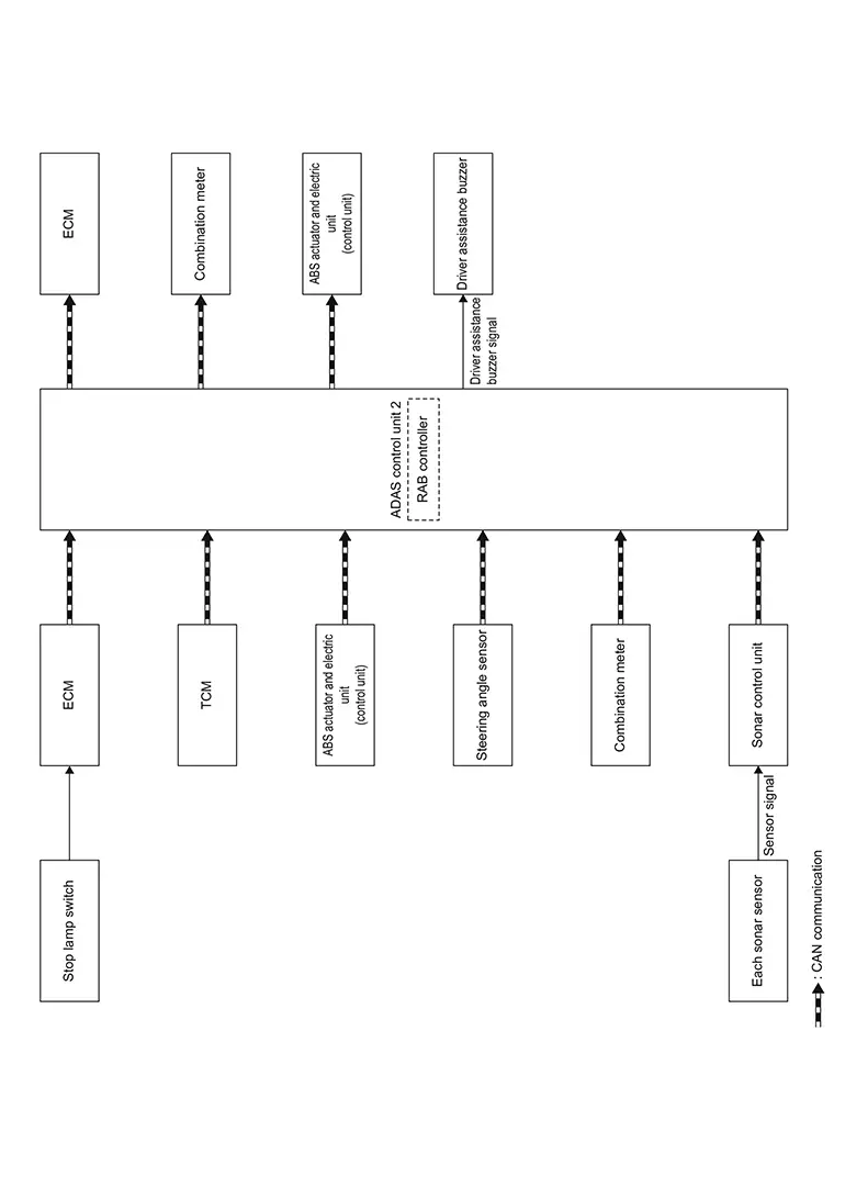
SYSTEM DIAGRAM
|
Component |
Function |
|---|---|
|
ADAS control unit 2 |
ADAS Control Unit 2 |
|
ECM |
Component Description |
|
TCM |
TCM |
|
Steering angle sensor |
Steering Angle Sensor |
|
Combination meter |
Combination Meter(4.2 inch Information Display) or Combination Meter(7 inch Information Display) |
|
ABS actuator and electric unit (control unit) |
ABS Actuator and Electric Unit (Control Unit) |
|
Stop lamp switch |
Stop Lamp Switch |
|
Driver assistance buzzer |
Driver Assistance Buzzer |
|
Sonar control unit |
Sonar Control Unit |
ADAS CONTROL UNIT 2 INPUT/OUTPUT SIGNAL ITEM
Input Signal Item
|
Transmit unit |
Signal name |
Description |
||
|---|---|---|---|---|
|
ECM |
CAN communication |
Closed throttle position signal |
Receives idle position state (ON/OFF) |
|
|
Accelerator pedal position signal |
Receives accelerator pedal position (angle) |
|||
|
Engine speed signal |
Receives engine speed |
|||
|
Stop lamp switch signal |
Receives an operational state of the brake pedal |
|||
|
TCM* |
CAN communication |
Input speed signal |
Receives the number of revolutions of input shaft |
|
|
Current gear position signal |
Receives a current gear position |
|||
|
Shift position signal |
Receives a selector lever position |
|||
|
Output shaft revolution signal |
Receives the number of revolutions of output shaft |
|||
|
ABS actuator and electric unit (control unit) |
CAN communication |
ABS malfunction signal |
Receives a malfunction state of ABS |
|
|
TCS malfunction signal |
Receives a malfunction state of TCS |
|||
|
VDC malfunction signal |
Receives a malfunction state of VDC |
|||
|
Nissan Sentra Vehicle speed signal (ABS) |
Receives wheel speeds of four wheels |
|||
|
Brake fluid pressure signal |
Receives brake fluid pressure |
|||
|
Steering angle sensor |
CAN communication |
Steering angle sensor signal |
Receives the number of revolutions, turning direction of the steering wheel |
|
|
Combination meter |
CAN communication |
System selection signal |
Receives a selection state of each item in “Emergency Brake” selected with the combination meter |
|
|
Sonar control unit |
CAN communication |
Sonar sensor signal |
Receives obstacle information (existence & distance) |
|
*: CVT models
Output Signal Item
|
Reception unit |
Signal name |
Description |
||
|---|---|---|---|---|
|
ECM |
CAN communication |
Torque down request signal |
Transmits a signal to control the engine torque. |
|
|
Stop lamp request signal |
Transmits a signal to activates the stop lamp. |
|||
|
ABS actuator and electric unit (control unit) |
CAN communication |
Brake fluid pressure control signal |
Transmits a brake fluid pressure control signal to activates the brake |
|
|
Combination meter |
CAN communication |
Meter display signal |
Transmits a signal to display a state of the system on the information display |
|
|
RAB warning lamp signal |
|
|||
|
Driver assistance buzzer |
Driver assistance buzzer signal |
Transmits a driver assistance buzzer signal to active the buzzer |
||
FUNCTION DESCRIPTION
-
The Rear Automatic Braking system can assist the driver when the Nissan Sentra vehicle is backing up and approaching objects directly behind the vehicle.
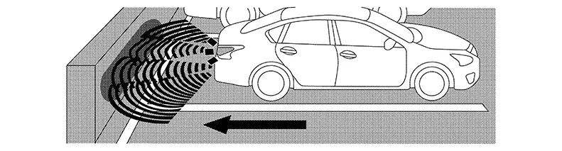
-
When the shift lever is in the R (Reverse) position and the Nissan Sentra vehicle speed is less than approximately 15 km/h (7 MPH), the RAB system operates.
-
The RAB system detects obstacles behind the Nissan Sentra vehicle using the sonar sensors.
-
If a risk of a collision with an obstacle is detected when own Nissan Sentra vehicle is backing up, the RAB system warning indicator will flash in the vehicle information display, and the system will chime three times.
-
The system will then automatically apply the brakes.
Note:
-
After the automatic brake application, the driver must depress the brake pedal to maintain brake pressure.
-
Driver can temporarily cancel the sonar function in the Nissan Sentra vehicle, but the RAB system will continue to operate.
-
OPERATION DESCRIPTION
-
Sonar detects a object approaching, and transmits the object detection signal to ADAS control unit 2 via CAN communication.
-
The ADAS control unit 2 performs the following operations according to the degree of possibility of a collision.
-
Transmits the driver assistance buzzer signal to the ADAS control unit 2 and sounds the warning system buzzer.
-
Transmits the meter display signal to the combination meter and displays the RAB system warning indicator.
-
Transmits the brake fluid pressure control signal to the ABS actuator and electric unit (control unit) via chassis control module and performs the brake control.
-
Transmits the stop lamp request signal to ECM and turn ON the stop lamp.
-
-
ON/OFF of RAB system is performed with the combination meter.
-
The RAB system will be automatically turned ON when the engine is restarted.
Operation Condition
ADAS control unit 2 performs the control when the following conditions are satisfied.
-
When the RAB system setting on the combination meter is ON.
-
When the Nissan Sentra vehicle speed is below approximately 15 km/h (9 MPH).
-
There is a possibility of a collision with the object backward.
No Operation Condition
The ADAS control unit 2 is not operate when the system is under the conditions of the no operation condition.
-
When the RAB system setting on the combination meter is OFF.
-
When the Nissan Sentra vehicle speed is above approximately 15 km/h (9 MPH).
-
When the object backward is not detected
Operation Cancellation Condition
The ADAS control unit 2 cancels the operation when the system is under any conditions of the operation cancellation condition.
-
When the system judges that the Nissan Sentra vehicle comes to a standstill by the system control.
-
When the system malfunction occurs.
-
When the sonar area of the rear bumper is dirty and the measurement of the distance between the object becomes difficult.
Fail-Safe (adas Control Unit 2)
Fail-safe (ADAS Control Unit 2)
Refer to Fail-safe (ADAS Control Unit 2).
Warning Lamp/indicator Lamp
Warning Lamp/Indicator Lamp
Warning Lamp/Indicator Lamp
|
Name |
Design |
Function |
|
|---|---|---|---|
|
RAB warning lamp |
|
|
|

Other materials:
Rear Bumper
Exploded View
Exploded View
EXCEPT FOR SR
1.
Rear bumper side bracket (LH)
2.
Rear bumper reinforcement support
(L ...
P0746-00 Pressure Control Solenoid a
Dtc Description
DTC Description
DTC DETECTION LOGIC
DTC
CONSULT screen terms
(Trouble diagnosis
content)
DTC detection
conditi ...
Basic Inspection. Diagnosis and Repair Work Flow
Diagnosis and Repair Work Flow
Work Flow
Work Flow
OVERALL SEQUENCE
DETAILED FLOW
GET INFORMATION FOR SYMPTOM
Get the detailed information from the customer
about the symptom (the condition and the environment when
the incident/malfunction occurred) usi ...