Nissan Sentra B18 (2020-2025) Service Manual: Component Parts
Rear Automatic Braking System
Component Parts Location
Component Parts Location
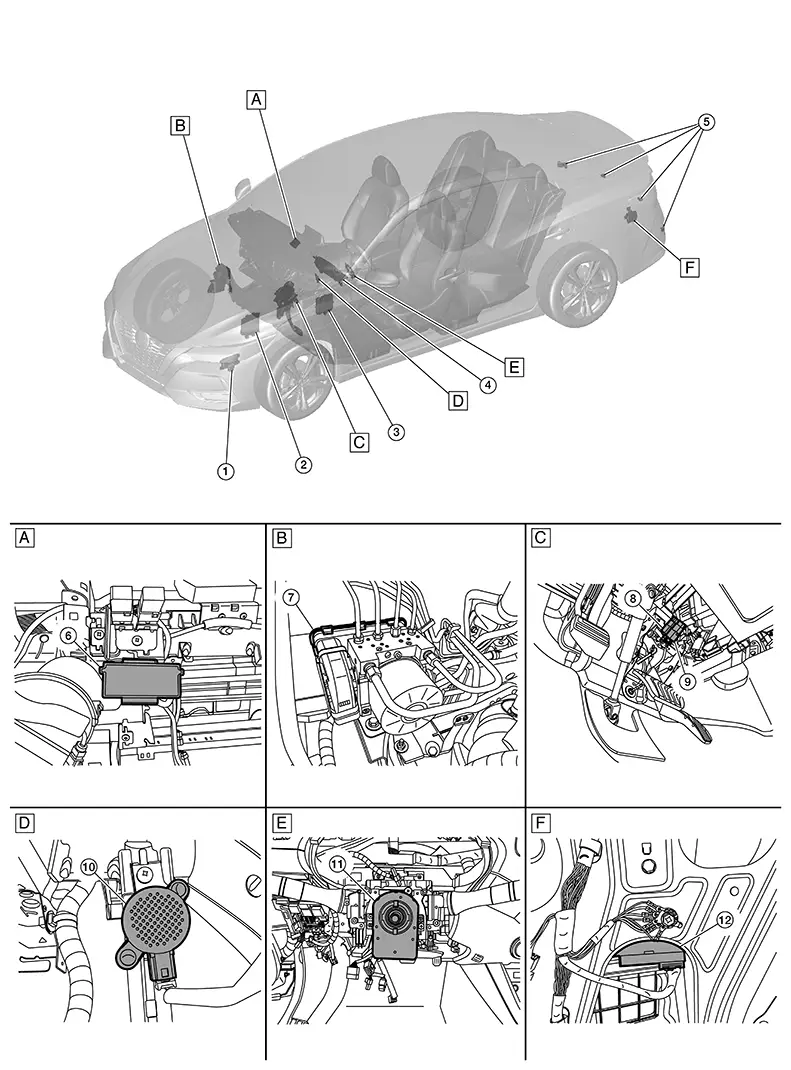
|
A. |
Right side of instrument panel (view with glove box assembly removed) |
B. |
RH side of engine compartment |
C. |
Brake pedal area |
|
D. |
Left side of instrument panel (view with instrument panel removed) |
E. |
Left side of instrument panel (view with steering wheel removed) |
F. |
Left side of luggage compartment (view with trunk side finisher LH removed) |
|
No. |
Component |
Function |
|---|---|---|
|
1. |
TCM (Transmission Control Module) |
CVT control related signal is transmitted to distance sensor via CAN communication. Refer to Component Parts Location for detailed component location. |
|
2. |
ECM (Engine Control Module) |
When Rear Automatic Braking operates, an engine torque down request signal is received from the distance sensor. Refer to Component Parts Location for detailed component location. |
|
3. |
BCM (Body Control Module) |
Stop lamp switch signal is transmitted to the via CAN communication. Refer to Component Parts Location for detailed component location. |
|
4. |
Combination meter |
Performs the following operations using the signals received from the distance sensor via the CAN communication:
Refer to Component Parts Location or (Type A) Component Parts Location (Type B) for detailed component location. |
|
5. |
Sonar sensors |
Refer to Component Parts Location for detailed component location. |
|
6. |
ADAS (Advanced Driver Assistant System) control unit |
Refer to ADAS Control Unit for detailed component location. |
|
7. |
ABS (Anti-lock Braking System) actuator and electric unit (control unit) |
Refer to Component Parts Location. |
|
8. |
Brake pedal position switch |
Detects the operation status of brake pedal and transmits converted electric signal to ABS actuator and electric unit (control unit). |
|
9. |
Stop lamp switch |
Refer to Stop Lamp Switch. |
|
10. |
Sonar buzzer |
Refer to Component Parts Location for detailed component location. |
|
11. |
Steering angle sensor |
Refer to Steering Angle Sensor. |
|
12. |
Sonar control unit |
Sonar sensor signals are received by the sonar control unit and transmitted to the combination meter via CAN communication for the RAB operation. Refer to Component Parts Location for detailed component location. |
Other materials:
P0139 Ho2s2
Dtc Description
DTC Description
The heated oxygen sensor 2 has a much longer switching time
between rich and lean than the air fuel ratio (A/F) sensor 1. The oxygen storage
capacity of the three way catalyst 1 causes the longer switching time. To judge
the malfunctions of heated oxy ...
Accelerator Control System. Removal and Installation. Accelerator Control System
Accelerator Control System
Exploded View
Exploded View
1.
Accelerator pedal
assembly
2.
Brake pedal bracket
...
Magnet Clutch
Component Function Check
Component Function Check
CHECK MAGNET CLUTCH OPERATION
Perform auto active test of IPDM E/R. Refer to CONSULT Function (IPDM E/R).
Does it operate normally?
YES >>
Inspection End.
NO > ...