Nissan Sentra B18 (2020-2025) Service Manual: System
Cvt Control System
System Description
System Description
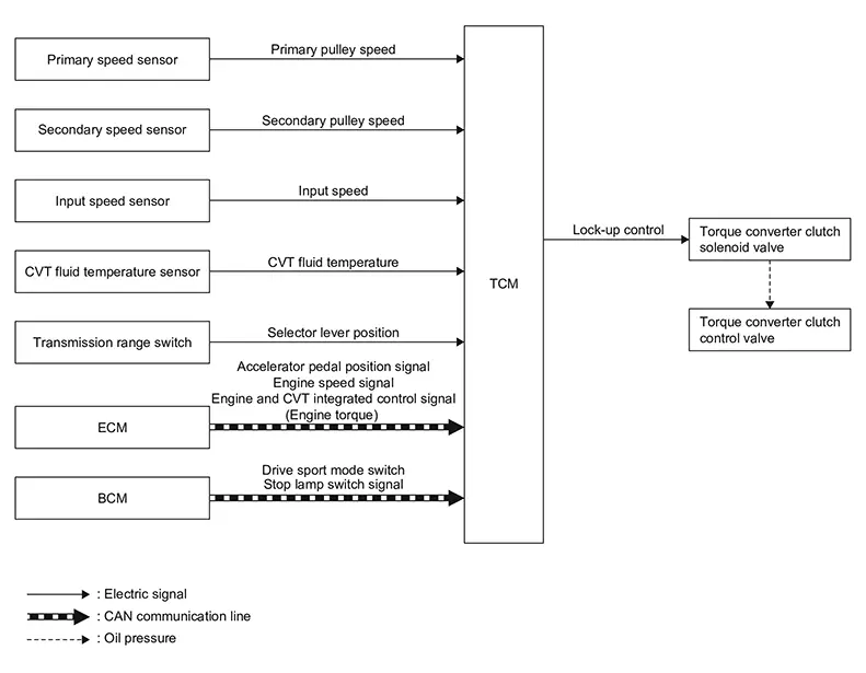
SYSTEM DIAGRAM
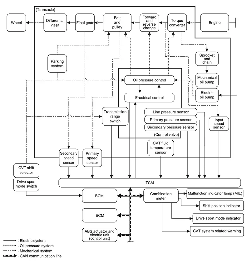
|
Name |
Function |
|---|---|
|
TCM |
TCM |
|
Transmission range switch |
Transmission Range Switch |
|
Primary speed sensor |
Primary Speed Sensor |
|
secondary speed sensor |
Secondary Speed Sensor |
|
Input speed sensor |
Input Speed Sensor |
|
Electric oil pump |
Electric Oil Pump |
|
CVT fluid temperature sensor |
CVT Fluid Temperature Sensor |
|
Primary pressure sensor |
Primary Pressure Sensor |
|
Secondary pressure sensor |
Secondary Pressure Sensor |
|
Line pressure sensor |
Line Pressure Sensor |
|
Primary pressure solenoid valve |
Primary Pressure Solenoid Valve |
|
Secondary pressure solenoid valve |
Secondary Pressure Solenoid Valve |
|
Select solenoid valve |
Select Solenoid Valve |
|
Torque converter clutch solenoid |
Torque Converter Clutch Solenoid |
|
Line pressure solenoid valve |
Line Pressure Solenoid Valve |
|
Drive sport mode switch |
Drive Sport Mode Switch |
|
Shift position indicator |
Shift Position Indicator |
|
ECM |
Mainly transmits the following signal to TCM via CAN communication.
Mainly receives the following signal from TCM via CAN communication.
|
|
BCM |
Mainly transmits the following signal to TCM via CAN communication.
|
|
ABS actuator and electric unit (control unit) |
Mainly transmits the following signals to TCM via CAN communication.
|
|
Combination meter |
Mainly receives the following signals from TCM via CAN communication.
|
MAIN CONTROL CONTENTS OF TCM
|
Controls |
Reference |
|
Line pressure control |
System Description |
|
Shift control |
System Description |
|
Select control |
System Description |
|
Lock-up control |
System Description |
|
ECO mode control |
ECO Mode Switch |
|
STOP START SYSTEM |
System Description |
|
Fail-safe |
Fail-safe |
|
Self-diagnosis function |
CONSULT Function |
|
Communication function with CONSULT |
CONSULT Function |
LIST OF CONTROL ITEMS AND INPUT/OUTPUT
|
Control Item |
Line pressure control |
Shift control |
Select control |
Lock-up control |
Fail-safe function* |
|
|---|---|---|---|---|---|---|
|
Input |
Engine torque signal (CAN communication) |
├Ś |
├Ś |
├Ś |
├Ś |
├Ś |
|
Engine speed signal (CAN communication) |
├Ś |
├Ś |
├Ś |
├Ś |
├Ś |
|
|
Accelerator pedal position signal (CAN communication) |
├Ś |
├Ś |
├Ś |
├Ś |
||
|
Closed throttle position signal (CAN communication) |
├Ś |
├Ś |
├Ś |
|||
|
Stop lamp switch signal (CAN communication) |
├Ś |
├Ś |
├Ś |
├Ś |
||
|
Primary pressure sensor |
├Ś |
├Ś |
||||
|
Secondary pressure sensor |
├Ś |
├Ś |
├Ś |
|||
|
Line pressure sensor |
├Ś |
├Ś |
||||
|
CVT fluid temperature sensor |
├Ś |
├Ś |
├Ś |
├Ś |
├Ś |
|
|
Primary speed sensor |
├Ś |
├Ś |
├Ś |
├Ś |
├Ś |
|
|
Secondary speed sensor |
├Ś |
├Ś |
├Ś |
├Ś |
||
|
Input speed sensor |
├Ś |
├Ś |
├Ś |
├Ś |
├Ś |
|
|
Transmission range switch |
├Ś |
├Ś |
├Ś |
├Ś |
├Ś |
|
|
ECO mode switch signal (CAN communication) |
├Ś |
|||||
|
Drive sport mode switch signal (CAN communication) |
├Ś |
|||||
|
Output |
Line pressure solenoid valve |
├Ś |
├Ś |
├Ś |
├Ś |
|
|
Primary pressure solenoid valve |
├Ś |
├Ś |
├Ś |
|||
|
Torque converter clutch solenoid |
├Ś |
├Ś |
||||
|
Secondary pressure solenoid valve |
├Ś |
├Ś |
├Ś |
|||
|
Select solenoid valve |
├Ś |
├Ś |
||||
|
Electric oil pump |
├Ś |
├Ś |
||||
|
Shift position indicator (CAN communication) |
├Ś |
|||||
|
ECO mode indicator lamp signal (CAN communication) |
├Ś |
|||||
|
Drive sport mode indicator signal (CAN communication) |
├Ś |
|||||
*: If these input/output signals show errors, TCM activates the fail-safe function.
Fail-Safe
Fail-safe
Fail-safe function
TCM has a fail-safe mode. The mode functions so that operation can be continued even if the signal circuit of the main electronically controlled input/output parts is damaged.
If the Nissan Sentra vehicle shows following behaviors including ŌĆ£poor accelerationŌĆØ, a malfunction of the applicable system is detected by TCM and the Nissan Sentra vehicle may be in a fail-safe mode. At this time, check the DTC code and perform inspection and repair according to the malfunction diagnosis procedures.
|
DTC |
Nissan Sentra Vehicle behavior |
Conditions of vehicle |
|
|---|---|---|---|
|
P0604 |
00 |
|
ŌĆö |
|
P0605 |
00 |
|
ŌĆö |
|
P0606 |
00 |
|
ŌĆö |
|
P060A |
00 |
|
ŌĆö |
|
P062F |
00 |
|
ŌĆö |
|
P0705 |
00 |
|
ŌĆö |
|
P0706 |
00 |
|
ŌĆö |
|
P0711 |
00 |
|
Engine coolant temperature when engine start: Temp. Ōēź 10┬░C (50┬░F) |
|
Engine coolant temperature when engine start: ŌłÆ35┬░C (ŌłÆ31┬░F) Ōēż Temp. < 10┬░C (50┬░F) |
||
|
Engine coolant temperature when engine start: Temp. <ŌłÆ35┬░C (ŌłÆ31┬░F) |
||
|
P0712 |
00 |
|
Engine coolant temperature when engine start: Temp. Ōēź 10┬░C (50┬░F) |
|
Engine coolant temperature when engine start: ŌłÆ35┬░C (ŌłÆ31┬░F) Ōēż Temp. < 10┬░C (50┬░F) |
||
|
Engine coolant temperature when engine start: Temp. <ŌłÆ35┬░C (ŌłÆ31┬░F) |
||
|
P0713 |
00 |
|
Engine coolant temperature when engine start: Temp. Ōēź 10┬░C (50┬░F) |
|
Engine coolant temperature when engine start: ŌłÆ35┬░C (ŌłÆ31┬░F) Ōēż Temp. < 10┬░C (50┬░F) |
||
|
Engine coolant temperature when engine start: Temp. <ŌłÆ35┬░C (ŌłÆ31┬░F) |
||
|
P0715 |
00 |
|
ŌĆö |
|
P0716 |
00 |
|
ŌĆö |
|
P0717 |
00 |
|
ŌĆö |
|
P0718 |
00 |
|
ŌĆö |
|
P0740 |
00 |
|
ŌĆö |
|
P0741 |
00 |
|
ŌĆö |
|
P0742 |
00 |
|
ŌĆö |
|
P0746 |
00 |
|
ŌĆö |
|
P0747 |
00 |
|
ŌĆö |
|
P0776 |
00 |
|
Nissan Sentra Vehicle speed < 40 km/h (25 MPH) or Input speed < 1300 rpm |
|
Other then the above |
||
|
P0777 |
00 |
|
Nissan Sentra Vehicle speed < 40 km/h (25 MPH) or Input speed < 1300 rpm |
|
Other then the above |
||
|
P0791 |
00 |
|
ŌĆö |
|
P0792 |
00 |
|
ŌĆö |
|
P0793 |
00 |
|
ŌĆö |
|
P0794 |
00 |
|
ŌĆö |
|
P0796 |
00 |
|
Nissan Sentra Vehicle speed < 40 km/h (25 MPH) or Input speed < 1300 rpm |
|
Other then the above |
||
|
P0797 |
00 |
|
Nissan Sentra Vehicle speed < 40 km/h (25 MPH) or Input speed < 1300 rpm |
|
Other then the above |
||
|
P07BF |
00 |
|
ŌĆö |
|
P07C0 |
00 |
|
ŌĆö |
|
P07C1 |
00 |
|
ŌĆö |
|
P07C2 |
00 |
|
ŌĆö |
|
P07C5 |
00 |
|
ŌĆö |
|
P07C6 |
00 |
|
ŌĆö |
|
P0845 |
00 |
|
ŌĆö |
|
P0846 |
00 |
|
ŌĆö |
|
P0847 |
00 |
|
ŌĆö |
|
P0848 |
00 |
|
ŌĆö |
|
P084A |
00 |
|
ŌĆö |
|
P084B |
00 |
|
ŌĆö |
|
P084C |
00 |
|
ŌĆö |
|
P084D |
00 |
|
ŌĆö |
|
P0863 |
00 |
|
ŌĆö |
|
P0870 |
00 |
|
ŌĆö |
|
P0871 |
00 |
|
ŌĆö |
|
P0872 |
00 |
|
ŌĆö |
|
P0873 |
00 |
|
ŌĆö |
|
P0890 |
00 |
|
ŌĆö |
|
P0960 |
00 |
|
ŌĆö |
|
P0961 |
00 |
|
When a malfunction occurs on the low oil pressure side |
|
When a malfunction occurs on the high oil pressure side |
||
|
P0962 |
00 |
|
ŌĆö |
|
P0963 |
00 |
|
ŌĆö |
|
P0964 |
00 |
|
Nissan Sentra Vehicle speed < 40 km/h (25 MPH) or Input speed < 1300 rpm |
|
Other then the above |
||
|
P0966 |
00 |
|
Nissan Sentra Vehicle speed < 40 km/h (25 MPH) or Input speed < 1300 rpm |
|
Other then the above |
||
|
P0967 |
00 |
|
Nissan Sentra Vehicle speed < 40 km/h (25 MPH) or Input speed < 1300 rpm |
|
Other then the above |
||
|
P0968 |
00 |
|
ŌĆö |
|
P0970 |
00 |
|
Nissan Sentra Vehicle speed < 40 km/h (25 MPH) or Input speed < 1300 rpm |
|
Other then the above |
||
|
P0971 |
00 |
|
Nissan Sentra Vehicle speed < 40 km/h (25 MPH) or Input speed < 1300 rpm |
|
Other then the above |
||
|
P1588 |
00 |
|
ŌĆö |
|
P159C |
00 |
|
ŌĆö |
|
P159D |
00 |
|
ŌĆö |
|
P17F0 |
07 |
|
ŌĆö |
|
P17F1 |
07 |
|
ŌĆö |
|
P17F2 |
07 |
|
ŌĆö |
|
P187E |
09 |
|
ŌĆö |
|
P188E |
00 |
|
ŌĆö |
|
P1AE0 |
61 |
Shift position indicator on combination meter is not displayed |
ŌĆö |
|
P271E |
00 |
Not changed from normal driving |
ŌĆö |
|
P2765 |
00 |
|
ŌĆö |
|
P2766 |
00 |
|
ŌĆö |
|
P2767 |
00 |
|
ŌĆö |
|
P2768 |
00 |
|
ŌĆö |
|
P2769 |
00 |
|
ŌĆö |
|
P2770 |
00 |
|
ŌĆö |
|
P27A1 |
00 |
|
ŌĆö |
|
P27A3 |
00 |
|
ŌĆö |
|
P27A4 |
00 |
|
ŌĆö |
|
P27A6 |
00 |
|
ŌĆö |
|
P27B3 |
00 |
|
ŌĆö |
|
P27B5 |
00 |
|
ŌĆö |
|
P27EB |
00 |
|
ŌĆö |
|
P27EC |
00 |
|
ŌĆö |
|
P27EF |
00 |
|
ŌĆö |
|
P27F0 |
00 |
|
ŌĆö |
|
P2808 |
00 |
|
ŌĆö |
|
P2809 |
00 |
|
ŌĆö |
|
P2812 |
00 |
|
ŌĆö |
|
P2814 |
00 |
|
ŌĆö |
|
P2815 |
00 |
|
ŌĆö |
|
P28ED |
00 |
|
ŌĆö |
|
P28EE |
00 |
|
ŌĆö |
|
U0073 |
00 |
|
ŌĆö |
|
U007A |
00 |
|
ŌĆö |
|
U0100 |
00 |
|
ŌĆö |
|
U0115 |
00 |
|
ŌĆö |
|
U0122 |
00 |
|
ŌĆö |
|
U0140 |
00 |
|
ŌĆö |
|
U0287 |
00 |
|
ŌĆö |
|
U0300 |
00 |
|
ŌĆö |
|
U1112 |
24 |
|
ŌĆö |
|
U2140 |
87 |
|
ŌĆö |
|
U2148 |
87 |
|
ŌĆö |
|
U214F |
87 |
|
ŌĆö |
|
U2153 |
87 |
|
ŌĆö |
|
U215B |
87 |
|
ŌĆö |
|
U2240 |
87 |
|
ŌĆö |
|
U2252 |
87 |
|
ŌĆö |
|
U2276 |
87 |
|
ŌĆö |
Protection Control
Protection Control
The TCM becomes the protection control status temporarily to protect the safety when the safety of TCM and transmission is lost. It automatically returns to the normal status if the safety is secured.
The TCM has the following protection control.
CONTROL FOR WHEEL SPIN
|
Control |
When a wheel spin is detected, the engine output and gear ratio are limited and the line pressure is increased. Limits engine output when a wheel spin occurs in any of right and left drive wheels. |
|
Nissan Sentra Vehicle behavior in control |
If the accelerator is kept depressing during wheel spin, the engine revolution and Nissan Sentra vehicle speed are limited to a certain degree. |
|
Normal return condition |
Wheel spin convergence returns the control to the normal control. |
TORQUE IS REDUCED WHEN DRIVING WITH THE REVERSE GEAR
|
Control |
Engine output is controlled according to a Nissan Sentra vehicle speed while reversing the vehicle. |
|
Vehicle behavior in control |
Power performance may be lowered while reversing the Nissan Sentra vehicle. |
|
Normal return condition |
Torque returns to normal by positioning the shift position in a range other than ŌĆ£RŌĆØ position. |
CONTROL WHEN FLUID TEMPERATURE IS HIGH
|
Control |
When the CVT fluid temperature is high, the gear shift permission maximum revolution and the maximum torque are reduced than usual to prevent increase of the oil temperature. |
|
Nissan Sentra Vehicle behavior in control |
Power performance may be lowered, compared to normal control. |
|
Normal return condition |
The control returns to the normal control when CVT fluid temperature is lowered. |
REVERSE PROHIBIT CONTROL
|
Control |
The reverse brake is controlled to avoid becoming engaged when the shift position is set in ŌĆ£RŌĆØ position while driving in forward direction at more than the specified speed. |
|
Nissan Sentra Vehicle behavior in control |
If the shift position is put at ŌĆ£RŌĆØ position when driving with the forward gear, the gear becomes neutral, not reverse. |
|
Normal return condition |
The control returns to normal control when the Nissan Sentra vehicle is driven at low speeds. (The reverse brake becomes engaged.) |
Line Pressure Control
System Description
System Description
SYSTEM DIAGRAM
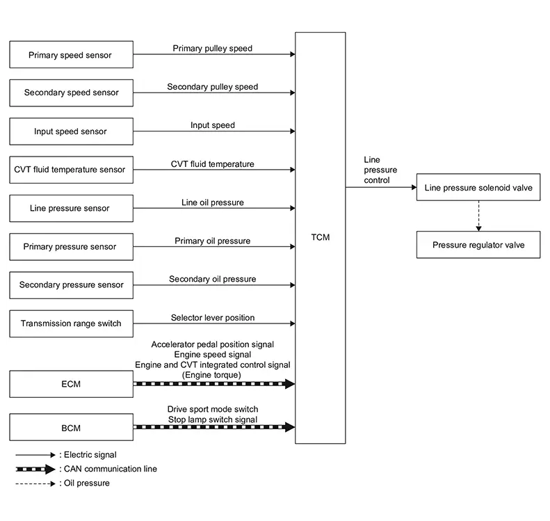
DESCRIPTION
Highly accurate line pressure control and secondary pressure control reduces friction for improvement of fuel economy.
Normal Oil Pressure Control
Appropriate line pressure and secondary pressure suitable for driving condition are determined based on the accelerator pedal position, engine speed, primary pulley (input) speed, secondary pulley (output) speed, Nissan Sentra vehicle speed, input torque, stop lamp switch signal, transmission range switch signal, lock-up signal, power voltage, target shift ratio, oil temperature, oil pressure, and drive sport mode switch signal.
Secondary Pressure Feedback Control
In normal oil pressure control and oil pressure control in shifting, highly accurate secondary pressure is determined by detecting the secondary pressure using an oil pressure sensor and by feedback control.
Shift Control
System Description
System Description
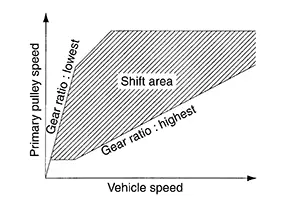
SYSTEM DIAGRAM
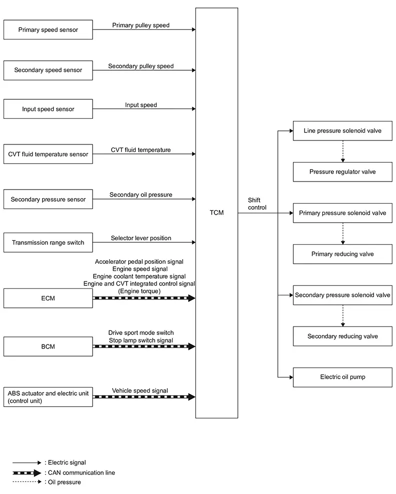
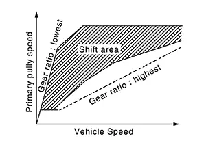
DESCRIPTION
To select the gear ratio that can give the driving force to meet driver's intent or Nissan Sentra vehicle situation, the vehicle driving condition such as vehicle speed or accelerator pedal position is detected and the most appropriate gear ratio is selected and the shifting method before reaching the speed is determined. The information is output to the primary pressure solenoid valve and secondary pressure solenoid valve to control the line pressure input/output to the pulley, to determine the pulley (movable pulley) position and to control the gear position.
Shift Position Function
-
D Position (Normal)
Gear shifting is performed in all shifting ranges from the lowest to the highest gear ratio.
-
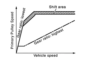
D Position (Drive sport mode)
The gear ratio is generally high by limiting the shifting range on the high side, and this always generates a large driving power.
-
L Position
By limiting the shifting range only to the lowest of the gear ratio, a large driving force and engine brake are obtained.
Hill Climbing And Descending Control
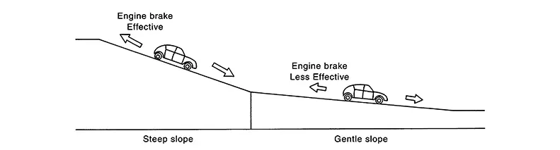
If a downhill is detected with the accelerator pedal is released, the system performs downshift to increase the engine brake force so that Nissan Sentra vehicle may not be accelerated more than necessary. If a climbing hill is detected, the system improves the acceleration performance in re-acceleration by limiting the gear shift range on the high side.
Note:
For engine brake control on a downhill, the control can be stopped with CONSULT.
Control In Acceleration
From change of the Nissan Sentra vehicle speed or accelerator pedal position, the acceleration request level of the driver or driving scene is evaluated. In start or acceleration during driving, the gear shift characteristics with linearity of revolution increase and Nissan Sentra vehicle speed increase are gained to improve the acceleration feel.
Select Control
System Description
System Description
SYSTEM DIAGRAM
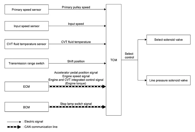
DESCRIPTION
Based on accelerator pedal angle, engine speed, primary pulley speed, and the input speed, the optimum operating pressure is set to reduce impact of a shift operation while shifting from ŌĆ£NŌĆØ (ŌĆ£PŌĆØ) to ŌĆ£DŌĆØ (ŌĆ£RŌĆØ) position.
Lock-Up Control
System Description
System Description
SYSTEM DIAGRAM
DESCRIPTION
-
Controls for improvement of the transmission efficiency by engaging the torque converter clutch in the torque converter and eliminating slip of the converter. Achieves comfortable driving with slip control of the torque converter clutch.
-
The oil pressure feed circuit for the torque converter clutch piston chamber is connected to the torque converter clutch control valve. The torque converter clutch control valve is switched by the torque converter clutch solenoid with the signal from TCM. This controls the oil pressure circuit, which is supplied to the torque converter clutch piston chamber, to the release side or engagement side.
-
If the CVT fluid temperature is low or the Nissan Sentra vehicle is in fail-safe mode due to malfunction, lock-up control is prohibited.
Lock-up engagement
In lock-up engagement, the torque converter clutch solenoid makes the torque converter clutch control valve locked up to generate the lock-up apply pressure. This pushes the torque converter clutch piston for engagement.
Lock-up release condition
In lock-up release, the torque converter clutch solenoid makes the torque converter clutch control valve non-locked up to drain the lock-up apply pressure. This does not engage the torque converter clutch piston.
Eco Mode Control
System Description
System Description
-
Driving mode that selects the shift schedule with priority on fuel economy which gives low engine revolution.
-
The gear shift line is not changed with the control mode change for the following conditions:
-
When the shift position is at D position and overdrive is OFF.
-
-
For details on ECO mode control, refer to System Description.
FAIL-SAFE
If a malfunction occurs in the system of CVT during ECO mode, the ECO mode indicator lamp turns OFF and the control switches to the normal mode control.
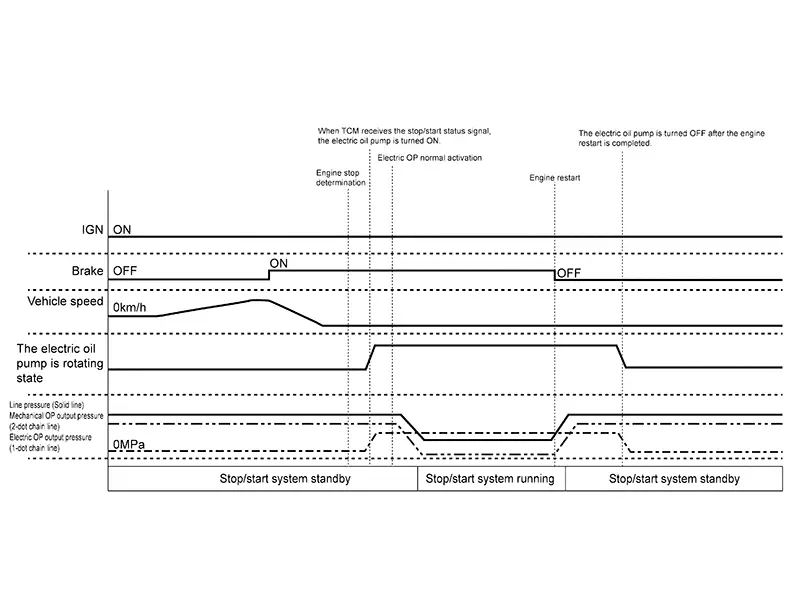
Stop/start System
System Description
System Description
STOP/START OPERATION PERMISSION CONDITION EVALUATED BY TCM
When TCM detects the vehicle status and stop/start system operation OK is determined, stop/start enable signal is sent to ECM through CAN communication.
|
Item |
Description |
Permission conditions |
|---|---|---|
|
CVT fluid temperature sensor |
CVT fluid temperature |
18Ōäā’Į×113Ōäā (64.4’Į×235.4Ōäē) |
|
Electric oil pump |
Malfunction |
Normal |
|
Pully ratio |
ŌĆö |
1.3 or more |
TIME CHART
Information Display (combination Meter)
Cvt System Warning
CVT System Warning
DESIGN/PURPOSE
CVT Malfunction Warning (Type A)
This warning is displayed when CVT system/function is not normal.
|
Design |
Warning Message |
||||||
|---|---|---|---|---|---|---|---|
|
|
CVT (AT) Malfunction Service now |
||||||

CVT Malfunction Warning (Type B)
This warning is displayed when CVT system/function is not normal.
|
Design |
Warning Message |
||||||
|---|---|---|---|---|---|---|---|
|
|
CVT (AT) Malfunction Stop safety |
||||||
CVT Malfunction Warning (Type C)
This warning is displayed when CVT system/function is not normal.
|
Design |
Warning Message |
||||||
|---|---|---|---|---|---|---|---|
|
|
Service CVT Power reduced |
||||||
CVT Hot Warning
This warning is displayed when CVT fluid temperature is high.
|
Design |
Warning Message |
||||||
|---|---|---|---|---|---|---|---|
|
|
CVT (AT) hot Power reduced |
||||||
CVT Stop The Nissan Sentra Vehicle Warning
This warning is displayed when CVT system judges the vehicle is reversed on an uphill road with the shift position in D (Drive), or moved forward on a downhill road with the shift position in R (Reverse).
|
Design |
Warning Message |
||||||
|---|---|---|---|---|---|---|---|
|
|
Stop the Nissan Sentra vehicle |
||||||
SYNCHRONIZATION WITH MASTER WARNING LAMP
Applicable
SYNCHRONIZATION WITH WARNING BUZZER
Not applicable
SYSTEM DIAGRAM
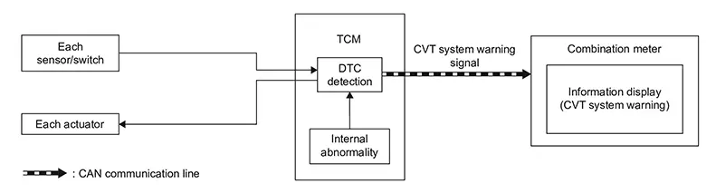
SIGNAL PATH
-
The TCM judges the condition of CVT system system/function based on the signal received from each sensor and the operating state of each actuator.
-
When the displaying conditions of the CVT system warning are satisfied, TCM transmits a CVT system warning signal to the combination meter via CAN communication.
-
The combination meter displays the CVT system warning according to the CVT system warning signal.
WARNING CONDITION
CVT Malfunction Warning Type A, Type B and Type C
When CVT system/function malfunction is detected at ignition ON.
Note:
For DTCs that the CVT system warning displays, refer to DTC Index.
CVT Hot Warning
When CVT fluid temperature becomes high and CVT protection control operates.
Stop The Nissan Sentra Vehicle Warning
When the CVT system judges the vehicle is reversed on an uphill road with the shift position in D (Drive), or moved forward on a downhill road with the shift position in R (Reverse).
WARNING CANCEL CONDITION
CVT Malfunction Warning Type A, Type B and Type C
Erase DTC
CVT Hot Warning
When CVT fluid temperature becomes low and CVT protection control stops.
Stop The Nissan Sentra Vehicle Warning
When the CVT system does not judge the vehicle is reversed on an uphill road with the shift position in D, or moved forward on a downhill road with the shift position in R.
Shift Position Indicator
Shift Position Indicator
PURPOSE
The shift position indicator displays the shift position of transaxle.

SYSTEM DIAGRAM
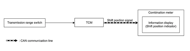
SIGNAL PATH
-
The TCM judges the shift position by the transmission range switch signal.
-
The TCM transmits the shift position signal to the combination meter via CAN communication.
-
The combination meter displays the shift position indicator on the information display, according to the signal.
INDICATOR OPERATING CONDITION
Ignition switch ON
INDICATOR CANCEL CONDITION
Ignition switch OFF
Drive Sport Mode Indicator
Drive Sport Mode Indicator
DESIGN/PURPOSE
Drive sport mode indicator informs the driver that the CVT control is in drive sport mode.
SYSTEM DIAGRAM
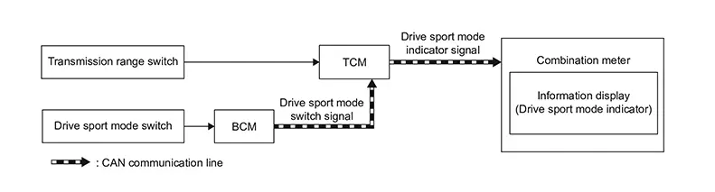
SIGNAL PATH
-
TCM judges the shift position by the transmission range switch.
-
BCM transmits a drive sport mode switch signal to the TCM.
-
TCM transmits a drive sport mode indicator signal to the combination meter when the drive sport mode switch is pressed in the D position.
INDICATOR OPERATING CONDITION
When all of the following conditions are satisfied:
-
Shift position: D position
-
Drive sport mode switch is pressed while drive sport mode indicator is not displayed.
INDICATOR CANCEL CONDITION
When any of the following conditions are satisfied:
-
Shift position: Except D position
-
Drive sport mode switch is pressed while drive sport mode indicator is displayed.
Warning/indicator/chime List
Warning Lamp/indicator Lamp
Warning Lamp/Indicator Lamp
|
Item |
Design |
Layout / Function |
|---|---|---|
|
Malfunction indicator lamp (MIL) |
|
Regarding the function, refer to Malfunction Indicator Lamp (MIL). |

Warning/indicator (on Information Display)
Warning/Indicator (On Information Display)
|
Item |
Function |
|---|---|
|
CVT system warning |
Refer to CVT System Warning. |
|
Shift position indicator |
Refer to Shift Position Indicator. |
|
Drive sport mode indicator |
Refer to Drive Sport Mode Indicator. |
Other materials:
Predictive Course Line Center Position Adjustment
Description
Description
Adjust the center position of the predictive
course line of the rear view monitor if it is shifted.
Work Procedure
Work Procedure
DRIVING
Drive the vehicle straight ahead 100 m (328.1 ft)
or more at a speed of ...
Front Fender
Exploded View
Exploded View
1.
Cowl top side trim cover
2.
Front fender baffle A
3.
...
P2297 Air Fuel Ratio Sensor 1
Dtc Description
DTC Description
DTC DETECTION LOGIC
DTC
CONSULT screen terms
(Trouble diagnosis
content)
DTC detection
conditi ...