Nissan Sentra B18 (2020-2025) Service Manual: Structure and Operation
Transaxle
Cross-Sectional View
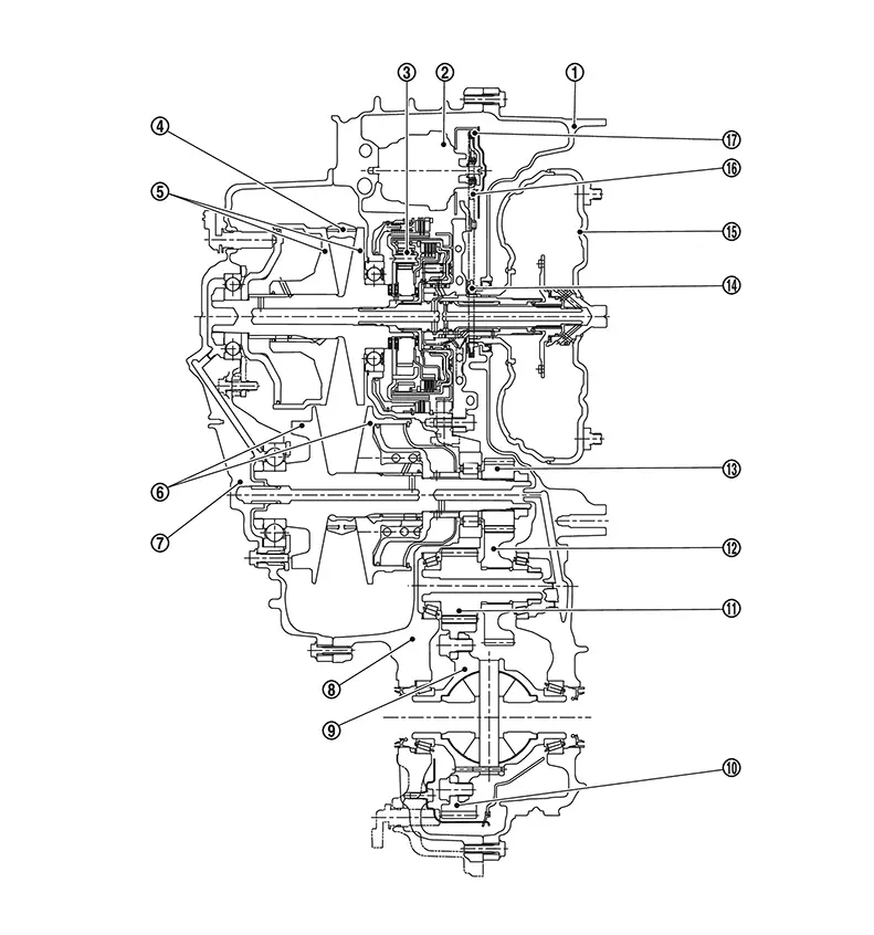
Cross-Sectional View
 |
Converter housing |
 |
Oil pump |
 |
Planetary gear |
 |
Steel belt |
 |
Primary pulley |
 |
Secondary pulley |
 |
Side cover |
 |
Transaxle case |
 |
Differential case |
 |
Final gear |
 |
Reduction gear |
 |
Idler gear |
 |
Output gear |
 |
Drive sprocket |
 |
Torque converter |
 |
Driven sprocket |
 |
Oil pump chain |
Operation Status
Operation Status
Ă—: Engaged or applied.|
shift position |
Parking mechanism |
Forward clutch |
Reverse brake |
Primary pulley |
Secondary pulley |
Steel belt |
Final drive |
|---|---|---|---|---|---|---|---|
|
P |
Ă— |
||||||
|
R |
Ă— |
Ă— |
Ă— |
Ă— |
Ă— |
||
|
N |
|||||||
|
D |
Ă— |
Ă— |
Ă— |
Ă— |
Ă— |
Transaxle Mechanism
Transaxle Mechanism
TORQUE CONVERTER (WITH LOCK-UP FUNCTION)
In the same way as a conventional A/T, the torque converter is a system that increases the engine torque and transmits the torque to the transaxle. A symmetrical 3-element, 1-stage, 2-phase type is used here.
OIL PUMP
Utilizes a vane-type oil pump that is driven by the engine through the oil pump drive chain in order to increase efficiency of pump discharge volume in low-speed zone and optimize pump discharge volume in high-speed zone. Discharged oil from oil pump is transmitted to control valve. It is used as the oil of primary and secondary pulley operation, the oil of clutch operation, and the lubricant for each part.
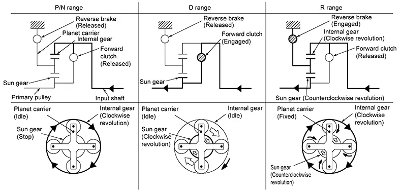
PLANETARY GEAR
-
A planetary gear type of forward/reverse selector mechanism is installed between the torque converter and primary pulley.
-
The power from the torque converter is input via the input shaft, operating a wet multi-plate clutch by means of hydraulic pressure to switch between forward and reverse driving.
Operation of Planetary gear
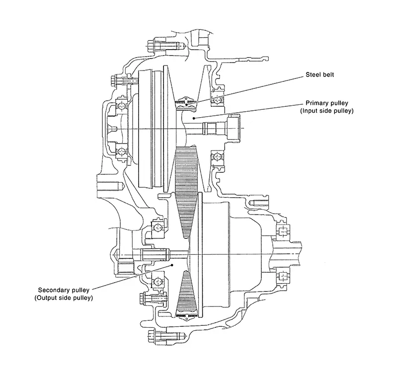
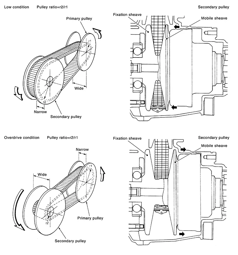
BELT AND PULLEY
It is composed of a pair of pulleys (the groove width is changed freely in the axial direction) and the steel belt (the steel plates are placed continuously and the belt is guided with the multilayer steel rings on both sides). The groove width changes according to wrapping radius of steel belt and pulley from low status to overdrive status continuously with non-step. It is controlled with the oil pressures of primary pulley and secondary pulley.
Steel Belt
It is composed of multiple steel plates and two
steel rings
and two
steel rings  stacked to a several number. The feature of this steel
belt transmits power with compression of the steel plate in contrast with
transmission of power in pulling with a rubber belt. Friction force is required
with the pulley slope to transmit power from the steel plate. The force is
generated with the following mechanism:
stacked to a several number. The feature of this steel
belt transmits power with compression of the steel plate in contrast with
transmission of power in pulling with a rubber belt. Friction force is required
with the pulley slope to transmit power from the steel plate. The force is
generated with the following mechanism:
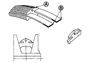
Oil pressure applies to the secondary pulley to nip the plate. ⇒The plate is pushed and extended outward. ⇒The steel ring shows withstands. ⇒Pulling force is generated on the steel ring. ⇒The plate of the primary pulley is nipped between the pulley. ⇒Friction force is generated between the steel belt and the pulley.
Therefore, responsibilities are divided by the steel plate that transmits the power with compression and the steel ring that maintains necessary friction force. In this way, the tension of the steel ring is distributed on the entire surface and stress variation is limited, resulting in good durability.
Pulley
The primary pulley (input shaft side) and the secondary pulley (output shaft side) have the shaft with slope (fixed cone surface), movable sheave (movable cone surface that can move in the axial direction) and oil pressure chamber at the back of the movable sheave.
The movable sheave slides on the shaft to change the groove width of the pulley. Input signals of engine load (accelerator pedal opening), primary pulley speed and secondary pulley speed change the operation pressures of the primary pulley and the secondary pulley, and controls the pulley groove width.
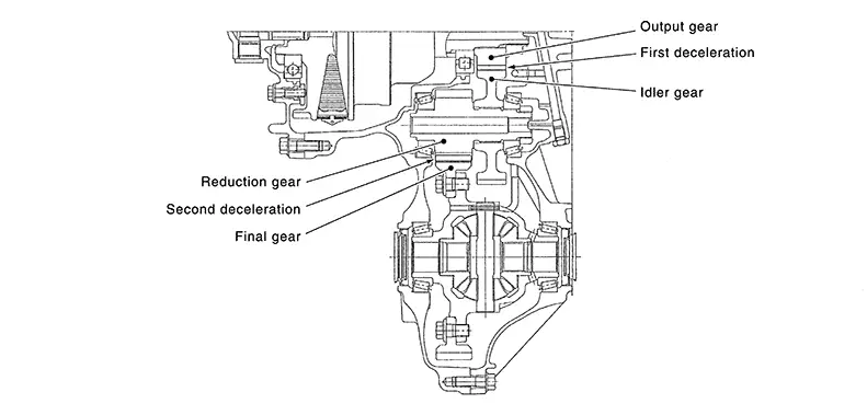
FINAL DRIVE AND DIFFERENTIAL
The deceleration gears are composed of 2 stages: primary deceleration (output gear, idler gear pair) and secondary deceleration (reduction gear, final gear pair). All of these gears are helical gears.
The lubrication oil is the same as the CVT fluid which lubricates the entire transaxle.
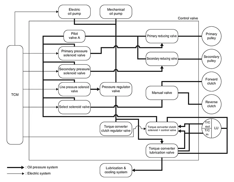
Oil Pressure System
Oil Pressure System
Oil pressure required for operation of the transaxle transmission mechanism is generated by mechanical oil pump, electric oil pump, oil pressure control valve, solenoid valve, etc.
Component Description
Component Description
|
Part name |
Function |
|---|---|
|
Torque converter |
Increases engine torque and transmits it to the transaxle. |
|
Mechanical oil pump |
Utilizes a vane-type oil pump that is driven by the engine through the oil pump drive chain in order to increase efficiency of pump discharge volume in low-speed zone and optimize pump discharge volume in high-speed zone. Discharged oil from oil pump is transmitted to control valve. It is used as the oil of primary and secondary pulley operation, the oil of clutch operation, and the lubricant for each part. |
|
Electric oil pump |
Utilizes a vane-type oil pump that is driven by electric energy in order to increase efficiency of pump discharge volume. This part has two functions as below.
|
|
Forward clutch |
The forward clutch is wet and multiple plate type clutch that consists of clutch drum, piston, drive plate, and driven plate. It is a clutch to move the Nissan Sentra vehicle forward by activating piston hydraulically, engaging plates, and directly connecting sun gear and input shaft. |
|
Reverse brake |
The reverse brake is a wet multiple-plate type brake that consists of transaxle case, piston, drive plate, and driven plate. It is a brake to move the Nissan Sentra vehicle in reverse by activating piston hydraulically, engaging plates, and fixing planetary gear. |
|
Internal gear |
The internal gear is directly connected to forward clutch drum. It is a gear that moves the outer edge of pinion planet of planet carrier. It transmits power to move the Nissan Sentra vehicle in reverse when the planet carrier is fixed. |
|
Planet carrier |
Composed of a carrier, pinion planet, and pinion shaft. This gear fixes and releases the planet carrier in order to switch between forward and reverse driving. |
|
Sun gear |
Sun gear is a set part with planet carrier and internal gear. It transmits transmitted force to primary fixed sheave. It rotates in forward or reverse direction according to activation of either forward clutch or reverse brake. |
|
Input shaft |
The input shaft is directly connected to forward clutch drum and transmits traction force from torque converter. In shaft center, there are holes for hydraulic distribution to primary pulley and hydraulic distribution for lockup ON/OFF. |
|
Primary pulley |
It is composed of a pair of pulleys (the groove width is changed freely in the axial direction) and the chain belt. The groove width changes according to wrapping radius of chain belt and pulley from low status to overdrive status continuously with non-step. It is controlled with the oil pressures of primary pulley and secondary pulley. |
|
Secondary pulley |
|
|
Steel belt |
|
|
Manual shaft |
When the manual shaft is in the P position, the parking rod that is linked to the manual shaft rotates the parking pole. When the parking pole rotates, it engages with the parking gear, fixing the parking gear. As a result, the secondary pulley that is integrated with the parking gear is fixed. |
|
Parking rod |
|
|
Parking pawl |
|
|
Parking gear |
|
|
Output gear |
The deceleration gears are composed of 2 stages: primary deceleration (output gear, idler gear pair) and secondary deceleration (reduction gear, final gear pair). All of these gears are helical gears. |
|
Idler gear |
|
|
Reduction gear |
|
|
Final gear |
|
|
Torque converter clutch regulator valve |
Adjusts the feed pressure to the torque converter to the optimum pressure corresponding to the driving condition. |
|
Pressure regulator valve |
Adjusts the discharge pressure from the oil pump to the optimum pressure (line pressure) corresponding to the driving condition. |
|
Torque converter clutch control valve |
Adjusts the torque converter engage and disengage pressures. |
|
Manual valve |
Distributes the clutch operation pressure to each circuit according to the shift position. |
|
Secondary reducing valve |
Reduces line pressure and adjusts secondary pressure. |
|
Primary reducing valve |
Reduces line pressure and adjusts primary pressure. |
|
Pilot valve A |
Reduces line pressure and adjusts pilot pressure to the solenoid valves listed below.
|
|
Primary pressure solenoid valve |
Reduces pilot A pressure and adjusts solenoid pressure. |
|
Secondary pressure solenoid valve |
|
|
Line pressure solenoid valve |
|
|
Select solenoid valve |
|
|
Torque converter clutch solenoid |
Torque converter clutch control valve is mainly controlled. |
|
Torque converter lubrication valve |
Switch lubrication circuit and supply lubrication flow to lubrication and cooling system. |
Fluid Warmer System
System Description
System Description
CVT FLUID WARMER SCHEMATIC
|
1. |
Engine |
2. |
Heater thermostat |
3. |
CVT oil warmer |
|
4. |
Transaxle |
A. |
Engine coolant |
B. |
CVT fluid |
COMPONENT DESCRIPTION
CVT Oil Warmer
-
The CVT oil warmer (1) is installed on the front part of transaxle assembly.
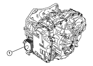
-
When engine is started while engine and CVT are cold, engine coolant temperature rises more quickly than CVT fluid temperature. CVT oil warmer is provided with two circuits for CVT and engine coolant respectively so that warmed engine coolant warms CVT quickly. This helps shorten CVT warming up time, improving fuel economy.
-
A cooling effect is obtained when CVT fluid temperature is high.
Heater Thermostat
-
The heater thermostat (1) is installed on the front part of transaxle assembly.
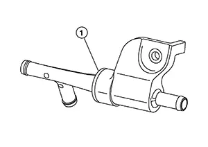
-
The heater thermostat opens and closes with set temperature.
Shift Lock System
System Description
System Description
-
The shift lock is the mechanism provided to prevent quick start of a vehicle by incorrect operation of a drive when the selector lever is in "P" position.
-
Selector lever can be shifted from the "P" position to another position when the following conditions are satisfied:
-
Ignition switch ON.
-
Stop lamp switch ON (brake pedal is depressed).
-
Press the selector button.
-
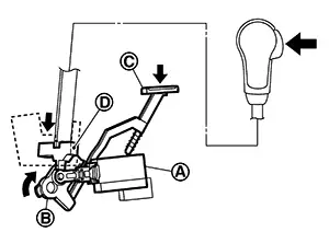
SHIFT LOCK OPERATION AT "P" POSITION
When brake pedal is not depressed (no selector operation allowed)
When the brake pedal is not depressed with the ignition switch ON, the shift lock solenoid (A) is OFF (not energized) and the solenoid rod (B) is extended with spring.
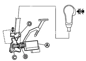
The connecting lock lever (C) is located at the position shown in the figure when the solenoid rod is extended. It prevents the movement of the detent rod (D). The selector lever cannot be shifted from the "P" position for this reason.
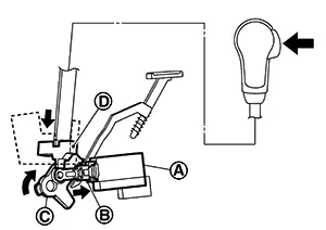
When brake pedal is depressed (selector lever operation allowed)
The shift lock solenoid (A) is turned ON (energized) when the brake pedal is depressed with the ignition switch ON. The solenoid rod (B) is compressed with the electromagnetic force. The connecting lock lever (C) rotates when the solenoid rod is compressed. Therefore, the detent rod (D) can be moved. The selector lever can be shifted to other positions for this reason.
"P" POSITION HOLD MECHANISM (IGNITION SWITCH LOCK)
The shift lock solenoid (A) is not energized when the ignition switch is in any position other than ON. The shift mechanism is locked and "P" position is held. The operation cannot be performed from "P" position if the brake pedal is depressed with the ignition switch ON when the operation system of shift lock solenoid is malfunctioning. However, the lock lever (B) is forcibly rotated and the shift lock is released when the shift lock release rod (C) is pressed from above. The selector operation from "P" position can be performed.
|
D |
: Detent rod |
CAUTION:
Use the shift lock release button only when the selector lever cannot be operated even if the brake pedal is depressed with the ignition switch ON.
Other materials:
Exterior. Symptom Diagnosis. Squeak and Rattle Trouble Diagnoses
Squeak and Rattle Trouble Diagnoses
Work Flow
Work Flow
CUSTOMER INTERVIEW
Interview the customer if possible, to determine
the conditions that exist when the noise occurs. Use the Diagnostic
Worksheet during the interview to document the facts and conditions
when the noise occu ...
System (power Door Lock System). System Description
System Description
System Description
INPUT SIGNAL AND OUTPUT SIGNAL
Signal name
Input
Output
Description
...
Handling Precaution
Precaution for Idle Start/stop System
Precaution for Idle Start/Stop System
PRECAUTIONS FOR IDLE START/STOP SYSTEM OPERATION
The operation of the idle start/stop system system needs to
satisfy various conditions. For details of the conditions, refer to System Description.
The idle start ...