Nissan Sentra B18 (2020-2025) Service Manual: Component Parts
Cvt Control System
Component Parts Location
Component Parts Location
 |
Shifter assembly |
 |
Transaxle assembly |
 |
Pedal periphery area |
 |
Type A* meter |
 |
Type B* meter |
||
 |
ABS actuator and electric unit (control unit) |
 |
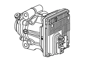
TCM |
 |
ECM |
 |
IPDM E/R |
 |
BCM |
 |
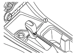
Drive sport mode switch |
 |
CVT fluid temperature sensor |
 |
Input speed sensor |
 |
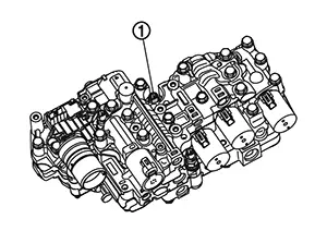
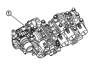
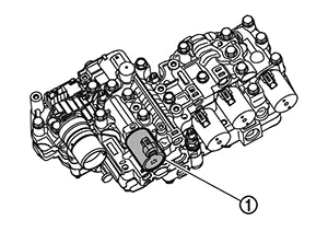
Control valve |
 |
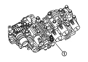
Electric oil pump |
 |
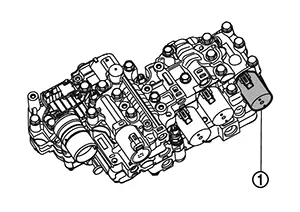
CVT unit connector |
 |
CVT unit connector (electric oil pump power supply and ground) |
 |
Primary speed sensor |
 |
Secondary speed sensor |
 |
Brake pedal position switch |
 |
Stop lamp switch |
 |
Accelerator pedal position sensor |
 |
Combination meter |
 |
Malfunction indicator lamp |
 |
Shift position indicator |
*: For details of TYPE, refer to Information.
Note:
-
The following components are included in control valve assembly.
-
Line pressure sensor
-
Primary pressure sensor
-
Secondary pressure sensor
-
Line pressure solenoid valve
-
Primary pressure solenoid valve
-
Secondary pressure solenoid valve
-
Torque converter clutch solenoid
-
Select solenoid valve
-
Tcm
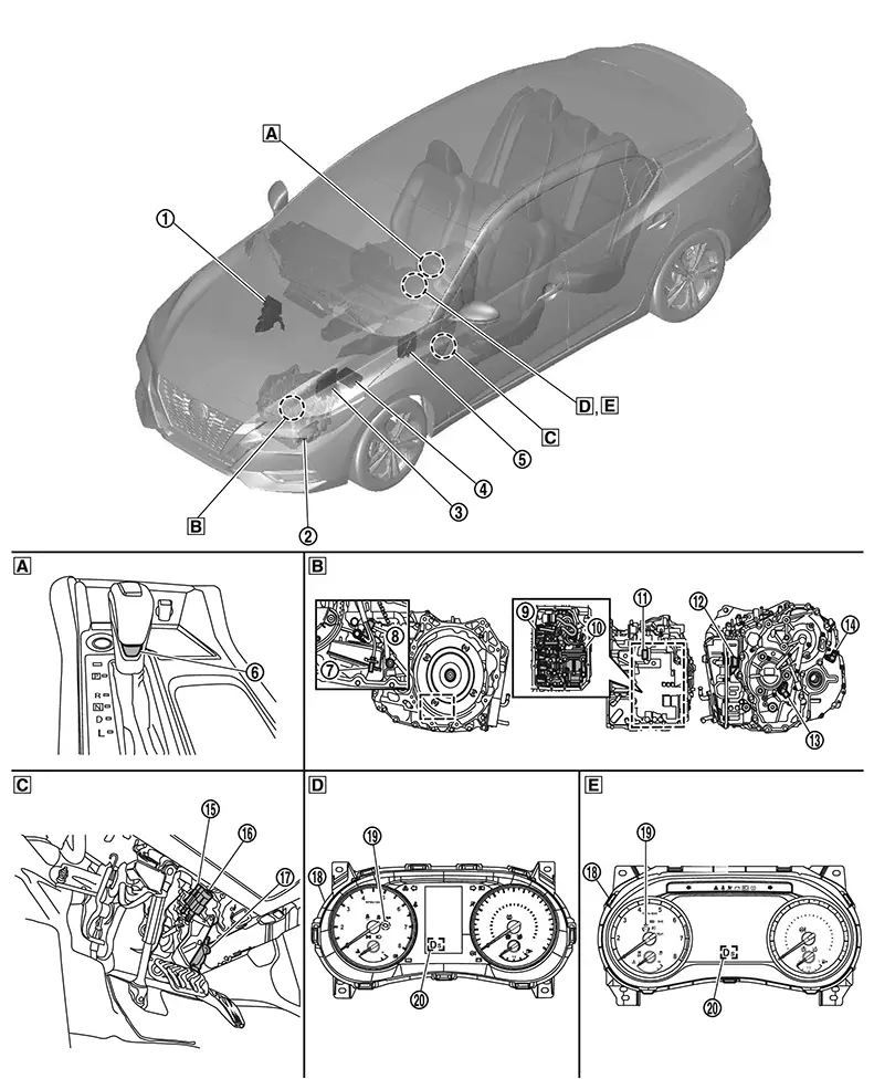
TCM
FUNCTIONS WITHIN THE SYSTEM
TCM judges the vehicle driving status based on the signals from the sensors, switches, and other control units, and the optimal transaxle control is performed.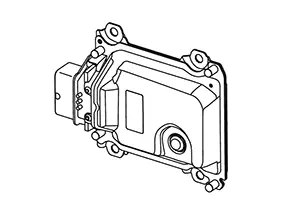
INDIVIDUAL FUNCTION WITHIN SYSTEM
The TCM consists of a microcomputer and connectors for signal input and output and for power supply.
INDIVIDUAL OPERATION
-
CVT control system. Refer to System Description.
-
Line pressure control system. Refer to System Description.
-
Shift change control system. Refer to System Description.
-
Select control system. Refer to System Description.
-
Lock-up control system. Refer to System Description.
-
Stop/start system. Refer to System Description.
COMPONENT PARTS LOCATION
The TCM is installed on the front side of battery.
Transmission Range Switch
Transmission Range Switch
FUNCTIONS WITHIN THE SYSTEM
The transmission range switch transfers select lever position to TCM as voltage signal.
INDIVIDUAL FUNCTION WITHIN SYSTEM
The transmission range switch detects the shift position.
INDIVIDUAL OPERATION
Detect the shift position by contact point which is switched according to turn of manual lever and manual shaft.
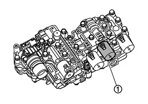
COMPONENT PARTS LOCATION
The transmission range switch is
installed to control valve.
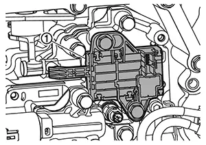
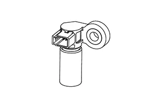
Primary Speed Sensor
Primary Speed Sensor
FUNCTIONS WITHIN THE SYSTEM
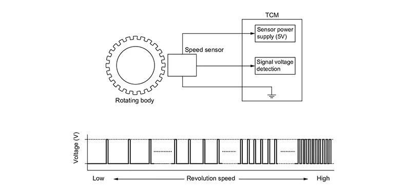
The primary speed sensor transfers detected primary pulley speed to TCM as pulse signal.
INDIVIDUAL FUNCTION WITHIN SYSTEM
The primary speed sensor detects primary pulley speed.
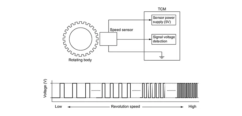
INDIVIDUAL OPERATION
The primary speed sensor generates an ON-OFF pulse signal according to the rotating body speed.
TCM judges the rotating body speed based on the pulse signal.
COMPONENT PARTS LOCATION
The primary speed sensor is installed to transaxle side cover.
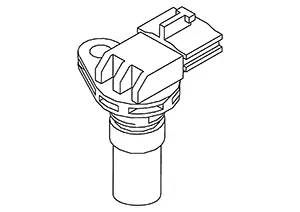
Secondary Speed Sensor
Secondary Speed Sensor
FUNCTIONS WITHIN THE SYSTEM
The secondary speed sensor transfers detected primary pulley speed to TCM as pulse signal.
INDIVIDUAL FUNCTION WITHIN SYSTEM
The secondary speed sensor detects final gear speed and transfers speed signal to TCM.
TCM calculates secondary pulley speed based on signal from secondary speed sensor.
INDIVIDUAL OPERATION
The secondary speed sensor generates an ON-OFF pulse signal according to the rotating body speed.
TCM judges the rotating body speed based on the pulse signal.
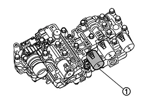
COMPONENT PARTS LOCATION
The secondary speed sensor is installed to the back side of transaxle case.
Cvt Fluid Temperature Sensor
CVT Fluid Temperature Sensor
FUNCTIONS WITHIN THE SYSTEM
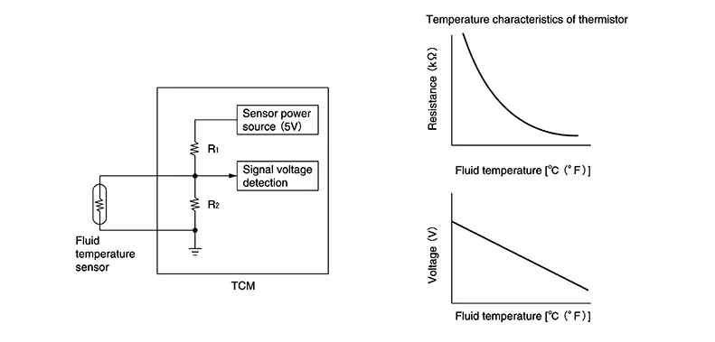
The CVT fluid temperature sensor transfers detected fluid temperature to TCM as signal voltage.
INDIVIDUAL FUNCTION WITHIN SYSTEM
The CVT fluid temperature sensor detects CVT fluid temperature in oil pan.
INDIVIDUAL OPERATION
The fluid temperature sensor uses a thermistor, and changes the voltage signal by converting changes in the CVT fluid temperature to a resistance value.
The voltage signal value change must be in proportion to the resistance value change.
TCM evaluates the CVT fluid temperature from the voltage signal value.
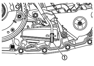
COMPONENT PARTS LOCATION
The CVT fluid temperature sensor is
installed to oil strainer.
Line Pressure Sensor
Line Pressure Sensor
FUNCTIONS WITHIN THE SYSTEM
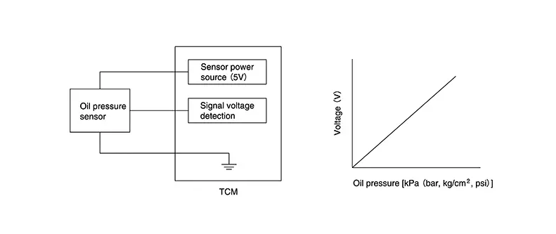
The line pressure sensor transfers detected line pressure to TCM as voltage signal.
INDIVIDUAL FUNCTION WITHIN SYSTEM
The line pressure sensor detects line pressure.
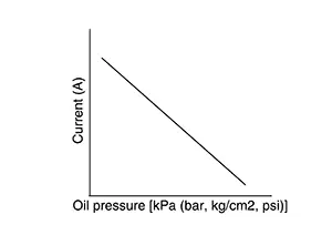
INDIVIDUAL OPERATION
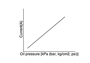
When pressure is applied to the diaphragm in the line pressure sensor, the strain gauge is deformed that produce voltage change.
TCM evaluates the line pressure based on the voltage change.
Voltage is increased along with pressure increase.
COMPONENT PARTS LOCATION
The line pressure sensor  is
installed to control valve.
is
installed to control valve.
Primary Pressure Sensor
Primary Pressure Sensor
FUNCTIONS WITHIN THE SYSTEM
The primary pressure sensor transfers detected the primary pressure to TCM as voltage signal.
INDIVIDUAL FUNCTION WITHIN SYSTEM
The primary pressure sensor detects the pressure applied to the primary pulley.
INDIVIDUAL OPERATION
When pressure is applied to the diaphragm in the primary pressure sensor, the strain gauge is deformed that produce voltage change.
TCM evaluates the primary pressure based on the voltage change.
Voltage is increased along with pressure increase.
COMPONENT PARTS LOCATION
The primary pressure sensor is
installed to control valve.
Secondary Pressure Sensor
Secondary Pressure Sensor
FUNCTIONS WITHIN THE SYSTEM
The secondary pressure sensor transfers detected secondary pressure to TCM as voltage signal.
INDIVIDUAL FUNCTION WITHIN SYSTEM
The secondary pressure sensor detects pressure applied to the secondary pulley.
INDIVIDUAL OPERATION
When pressure is applied to the diaphragm in the secondary pressure sensor, the strain gauge is deformed that produces voltage change.
TCM evaluates the secondary pressure based on the voltage change. Voltage is increased along with pressure increase.
COMPONENT PARTS LOCATION
The secondary pressure sensor is
installed to control valve.
Input Speed Sensor
Input Speed Sensor
FUNCTIONS WITHIN THE SYSTEM
The input speed sensor transfers detected input shaft speed to TCM as pulse signal.
INDIVIDUAL FUNCTION WITHIN SYSTEM
The input speed sensor detects input shaft speed.
INDIVIDUAL OPERATION
The input speed sensor generates an ON-OFF pulse signal according to the rotating body speed.
TCM judges the rotating body speed based on the pulse signal.
COMPONENT PARTS LOCATION
The input speed sensor is installed to the transaxle.
Primary Pressure Solenoid Valve
Primary Pressure Solenoid Valve
FUNCTIONS WITHIN THE SYSTEM
The primary pressure solenoid valve controls the primary reducing valve by TCM signal, that controls the primary pressure .
INDIVIDUAL FUNCTION WITHIN SYSTEM
The primary pressure solenoid valve controls the primary reducing valve.
For information about the primary reducing valve, Refer to Component Description.
INDIVIDUAL OPERATION
The primary pressure solenoid valve uses the linear solenoid valve [N/H (normal high) type].
COMPONENT PARTS LOCATION
The primary pressure solenoid valve is
installed to control valve.
Secondary Pressure Solenoid Valve
Secondary Pressure Solenoid Valve
FUNCTIONS WITHIN THE SYSTEM
The secondary pressure solenoid valve controls the secondary reducing valve by TCM signal, that controls secondary pressure.
INDIVIDUAL FUNCTION WITHIN SYSTEM
The secondary pressure solenoid valve controls the secondary reducing valve.
For information about the secondary reducing valve, Refer to Component Description.
INDIVIDUAL OPERATION
The secondary pressure solenoid valve uses the linear solenoid valve [N/H (normal high) type].
COMPONENT PARTS LOCATION
The secondary pressure solenoid valve is
installed to control valve.
Select Solenoid Valve
Select Solenoid Valve
FUNCTIONS WITHIN THE SYSTEM
The select solenoid valve adjusts the operating pressure of the forward clutch and reverse brake to switch forward/backward movement of Nissan Sentra vehicle.
INDIVIDUAL FUNCTION WITHIN SYSTEM
The select solenoid valve adjusts the operating pressure of the forward clutch and reverse brake.
INDIVIDUAL OPERATION
The select solenoid valve utilizes the linear solenoid valve [N/H (normal high) type].
COMPONENT PARTS LOCATION
The select solenoid valve is
installed to control valve.
Torque Converter Clutch Solenoid
Torque Converter Clutch Solenoid
FUNCTIONS WITHIN THE SYSTEM
The torque converter clutch solenoid controls the torque converter clutch control valve by TCM signal and adjusts engagement and disengagement pressure of torque converter.
INDIVIDUAL FUNCTION WITHIN SYSTEM
The torque converter clutch solenoid controls the torque converter clutch control valve.
For information about the torque converter clutch control valve, Refer to Component Description.
INDIVIDUAL OPERATION
The torque converter clutch solenoid utilizes an electromagnetic solenoid.
COMPONENT PARTS LOCATION
The torque converter clutch solenoid is installed to control valve.
Line Pressure Solenoid Valve
Line Pressure Solenoid Valve
FUNCTIONS WITHIN THE SYSTEM
The line pressure solenoid valve controls the pressure regulator valve by TCM signal, that controls the line pressure.
INDIVIDUAL FUNCTION WITHIN SYSTEM
The line pressure solenoid valve controls the pressure regulator valve.
For information about the pressure regulator valve, Refer to Component Description.
INDIVIDUAL OPERATION
The line pressure solenoid valve uses the linear solenoid valve [N/H (normal high) type].
COMPONENT PARTS LOCATION
The line pressure solenoid valve is
installed to control valve.
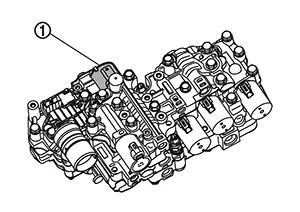
Electric Oil Pump
Electric Oil Pump
FUNCTIONS WITHIN THE SYSTEM
Command signal from TCM assists mechanical oil pump built-in transaxle to secure the required fluid pressure.
INDIVIDUAL FUNCTION WITHIN SYSTEM
Supply hydraulic pressure according to the request from TCM.
INDIVIDUAL OPERATION
-
Electric oil pump has a built-in brushless three-phase AC motor.
-
Operate by CAN signal from TCM.
-
Transmit the operating status to TCM as a CAN signal.
COMPONENT PARTS LOCATION
The electric oil pump is mounted inside the transaxle assembly.
Shift Position Indicator
Shift Position Indicator
TCM transmits shift position signal to combination meter via CAN communication. The actual shift position is displayed on combination meter according to the signal.
Drive Sport Mode Switch
Drive Sport Mode Switch
FUNCTIONS WITHIN THE SYSTEM
Drive sport mode switch controls drive sport mode ON/OFF.
INDIVIDUAL FUNCTION WITHIN SYSTEM
-
When the drive sport mode indicator on the combination meter is OFF and the drive sport mode switch is pressed, the drive sport mode is active and the drive sport mode indicator is ON.
-
When the drive sport mode indicator on the combination meter is ON and the drive sport mode switch is pressed, the drive sport mode is cancelled and the drive sport mode indicator is OFF.
INDIVIDUAL OPERATION
Drive sport mode switch is alternating ON/OFF push button switch.
COMPONENT PARTS LOCATION
The drive sport mode switch is installed to the selector lever knob.
Shift Lock System
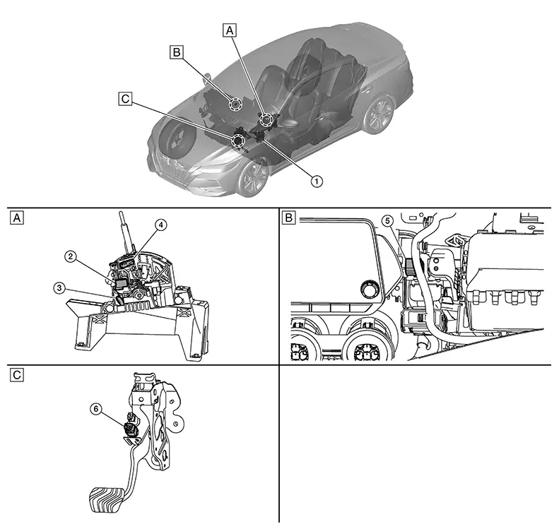
Component Parts Location
Component Parts Location
|
A. |
View of the CVT shift selector assembly removed from Nissan Sentra vehicle |
B. |
Behind the A/C control (With Remote Engine Start) |
C. |
View of the brake pedal assembly removed from Nissan Sentra vehicle |
|
No. |
Component |
Function |
|---|---|---|
|
1. |
BCM (Body Control Module) |
BCM controls remote start relay according to remote engine start signal. Refer to System Description. |
|
2. |
Shift lock solenoid |
It operates according to the signal from the stop lamp switch and moves the lock lever. |
|
3. |
Park position switch |
This switch closes to provide ground to the solenoid. |
|
4. |
Detent switch |
Detects that the CVT shift selector is in the "P" position. |
|
5. |
Remote start relay (if so equipped) |
Allows BCM to be ready to operate shift lock solenoid. |
|
6. |
Stop lamp switch |
|
Other materials:
Maintenance precautions
When performing any inspection, servicing, or maintenance work on your Nissan
Sentra, always exercise extreme care to avoid serious personal injury or accidental
damage to the vehicle. Routine maintenance plays an important role in the long-term
reliability, safety, and performance of the Niss ...
Power Supply and Ground Circuit
A/c Auto Amp.
Diagnosis Procedure
Diagnosis Procedure
CHECK A/C AUTO AMP. GROUND CIRCUIT
FOR OPEN
Ignition switch OFF.
Disconnect A/C auto amp. connector.
...
Handling Precaution
Precaution for Idle Start/stop System
Precaution for Idle Start/Stop System
PRECAUTIONS FOR IDLE START/STOP SYSTEM OPERATION
The operation of the idle start/stop system system needs to
satisfy various conditions. For details of the conditions, refer to System Description.
The idle start ...