Nissan Sentra B18 (2020-2025) Service Manual: System
Engine Control System
System Description
System Description
SYSTEM DIAGRAM
SYSTEM DESCRIPTION
-
The adopted system enables comprehensive engine control. ECM (engine control module) performs various controls such as fuel injection control, ignition timing control, idling engine speed control, EVAP purge control and etc., and this system communicates with control unit such as CVT, ABS, etc. via CAN communication line.
-
The adopted diagnostic system corresponding to OBD (on board diagnostic) system enables various function check and easily malfunction diagnosis in the engine control system.
|
Function |
Reference |
|---|---|
|
Fuel injection control |
System Description |
|
Fuel pressure control |
System Description |
|
Electric ignition control |
System Description |
|
EGR system |
System Description |
|
Idle speed control |
System Description |
|
Cooling fan control |
System Description |
|
Intake valve timing control |
System Description |
|
Exhaust valve timing control |
System Description |
|
Intake manifold runner control valve control |
System Description |
|
Engine protection control (Low engine oil pressure) |
System Description |
|
Air conditioning cut control |
System Description |
|
ASCD (Automatic speed control device) |
System Description |
|
ECO mode control |
System Description |
|
Engine/CVT/ABS total control |
System Description |
|
Evaporative emmision system |
System Description |
|
Fuel filler cap warning system |
System Description |
|
Power generation voltage variable control |
System Description |
|
Idle start/stop system |
System Description |
|
Information display |
System Description |
|
Warning/Indicator/Chime |
|
|
Fail-safe function |
Fail-safe |
|
On board diagnostic (OBD) system |
Diagnosis Description. |
Fail-Safe
Fail-safe
ENGINE CONTROL SYSTEM
Description
When a DTC is detected, ECM executes a mode (in the Fail-safe mode) applicable to the DTC. The fail-safe mode has the preset traveling control mode (accelerator angle variation and engine output limit), device fix mode and combustion control mode.
|
Fail safe mode |
Nissan Sentra Vehicle behavior |
Fail safe pattern |
|
|---|---|---|---|
|
Traveling control mode |
Accelerator angle variation control |
ECM controls the accelerator pedal depression speed to make it slower than actual speed. This causes a drop in accelerating performance and encourages the driver to repair malfunction. Note:
ECM does not control the accelerator pedal releasing speed. |
A |
|
Engine output control 1 |
ECM reduces the engine output, according to the rise in engine speed. This reduces the Nissan Sentra vehicle speed to encourage the driver to repair malfunction. Driving at 70 km/h (44 MPH) or more is possible. Note:
This value is a reference value converted from engine power to Nissan Sentra vehicle speed. Actual power limitation value differs due to the malfunctioning part and driving condition. |
B |
|
|
Engine output control 2 |
ECM reduces the engine output, according to the rise in engine speed. This reduces the Nissan Sentra vehicle speed to encourage the driver to repair malfunction. Driving at 40 km/h (25 MPH) or more is possible. Note:
This value is a reference value converted from engine power to Nissan Sentra vehicle speed. Actual power limitation value differs due to the malfunctioning part and driving condition. |
C |
|
|
Device fix mode |
|
D |
|
|
Combustion control mode |
Stratified charge combustion control at starting |
No stratified charge combustion at starting (cold start). |
E |
|
Idle speed control |
Stops feedback control of idle speed and controls with specified speed. |
F |
|
|
Recovery speed control at decelerating |
Stops recovery speed control by the fuel cut at decelerating and controls with specified speed. |
||
|
Idle neutral control |
Stops idle neutral control. |
||
|
Ignition timing correction control |
Partially controls ignition timing control. |
G |
|
|
Retardation control |
Controls ignition timing delay control in the intermediate water temperature range. |
||
Fail Safe List
├Ś:Applicable ŌĆö: Not applicable|
DTC No. |
Detected items |
Nissan Sentra Vehicle behavior |
||||||||
|---|---|---|---|---|---|---|---|---|---|---|
|
Pattern |
Others |
|||||||||
|
A |
B |
C |
D |
E |
F |
G |
||||
|
P0010 |
Electric intake valve timing module |
ŌĆö |
ŌĆö |
ŌĆö |
├Ś |
├Ś |
ŌĆö |
ŌĆö |
ECM stops the electric valve timing control. (The camshaft returns to the position of most retard angle.) |
|
|
ŌĆö |
ŌĆö |
ŌĆö |
├Ś |
├Ś |
├Ś |
ŌĆö |
||||
|
P0011 P0012 P052A P052B |
Intake valve timing control |
ŌĆö |
ŌĆö |
ŌĆö |
├Ś |
ŌĆö |
ŌĆö |
ŌĆö |
||
|
P0014 P0015 |
Exhaust valve timing control |
ŌĆö |
ŌĆö |
ŌĆö |
├Ś |
ŌĆö |
ŌĆö |
ŌĆö |
ŌĆö |
|
|
P0078 |
Exhaust valve timing control solenoid valve |
ŌĆö |
ŌĆö |
ŌĆö |
├Ś |
ŌĆö |
ŌĆö |
ŌĆö |
ŌĆö |
|
|
P0087 P0088 P0090 |
FRP control system |
├Ś |
ŌĆö |
ŌĆö |
├Ś |
├Ś |
ŌĆö |
ŌĆö |
ŌĆö |
|
|
P0102 P0103 |
Mass air flow sensor circuit |
├Ś |
├Ś |
ŌĆö |
├Ś |
├Ś |
├Ś |
├Ś |
ŌĆö |
|
|
P0117 P0118 |
Engine coolant temperature sensor circuit |
ŌĆö |
ŌĆö |
ŌĆö |
ŌĆö |
├Ś |
├Ś |
ŌĆö |
ŌĆö |
|
|
P0122 P0123 P0222 P0223 P2135 |
Throttle position sensor |
ŌĆö |
ŌĆö |
ŌĆö |
├Ś |
ŌĆö |
ŌĆö |
ŌĆö |
The ECM controls the electric throttle control actuator in regulating the throttle opening in order for the idle position to be within +10 degrees. The ECM regulates the opening speed of the throttle valve to be slower than the normal condition. So, the acceleration will be poor. |
|
|
P0171 P0172 |
Fuel injection system |
├Ś |
ŌĆö |
ŌĆö |
ŌĆö |
├Ś |
├Ś |
ŌĆö |
ŌĆö |
|
|
P0190 |
FRP sensor |
├Ś |
ŌĆö |
ŌĆö |
├Ś |
├Ś |
├Ś |
ŌĆö |
ŌĆö |
|
|
P0197 P0198 |
Engine oil temperature sensor |
ŌĆö |
ŌĆö |
ŌĆö |
ŌĆö |
ŌĆö |
ŌĆö |
ŌĆö |
Intake and exhaust valve timing control does not function. |
|
|
P0201 P0202 P0203 P0204 |
Injector |
├Ś |
ŌĆö |
ŌĆö |
├Ś |
├Ś |
ŌĆö |
ŌĆö |
ŌĆö |
|
|
P0300 |
Misfire |
├Ś |
ŌĆö |
ŌĆö |
ŌĆö |
├Ś |
├Ś |
ŌĆö |
ŌĆö |
|
|
P0335 |
Crankshaft position sensor |
ŌĆö |
ŌĆö |
ŌĆö |
├Ś |
├Ś |
ŌĆö |
ŌĆö |
ŌĆö |
|
|
ŌĆö |
ŌĆö |
ŌĆö |
├Ś |
├Ś |
├Ś |
ŌĆö |
||||
|
ŌĆö |
ŌĆö |
ŌĆö |
├Ś |
ŌĆö |
ŌĆö |
ŌĆö |
||||
|
P0340 |
Intake camshaft position sensor |
ŌĆö |
ŌĆö |
ŌĆö |
├Ś |
├Ś |
ŌĆö |
ŌĆö |
ŌĆö |
|
|
ŌĆö |
ŌĆö |
ŌĆö |
├Ś |
├Ś |
├Ś |
ŌĆö |
||||
|
ŌĆö |
ŌĆö |
ŌĆö |
├Ś |
ŌĆö |
ŌĆö |
ŌĆö |
||||
|
P0365 |
Exhaust camshaft position sensor |
ŌĆö |
ŌĆö |
ŌĆö |
├Ś |
ŌĆö |
ŌĆö |
ŌĆö |
ŌĆö |
|
|
P0401 P0402 |
EGR system |
ŌĆö |
ŌĆö |
ŌĆö |
├Ś |
ŌĆö |
ŌĆö |
ŌĆö |
ŌĆö |
|
|
P0404 |
EGR volume control valve |
├Ś |
├Ś |
├Ś |
├Ś |
├Ś |
├Ś |
ŌĆö |
ŌĆö |
|
|
P044A P044B P044C P044D P044E |
EGR volume control valve position sensor |
├Ś |
ŌĆö |
ŌĆö |
├Ś |
ŌĆö |
ŌĆö |
ŌĆö |
ŌĆö |
|
|
P0500 |
Nissan Sentra Vehicle speed sensor |
├Ś |
ŌĆö |
ŌĆö |
ŌĆö |
├Ś |
├Ś |
ŌĆö |
ŌĆö |
|
|
P0524 |
Engine oil pressure |
ŌĆö |
ŌĆö |
ŌĆö |
ŌĆö |
ŌĆö |
ŌĆö |
ŌĆö |
|
|
|
P059F |
Active grille shutter |
ŌĆö |
ŌĆö |
ŌĆö |
ŌĆö |
ŌĆö |
ŌĆö |
ŌĆö |
|
|
|
P0603 P0607 |
ECM |
├Ś |
├Ś |
ŌĆö |
ŌĆö |
ŌĆö |
ŌĆö |
ŌĆö |
ŌĆö |
|
|
P0604 |
ŌĆö |
ŌĆö |
ŌĆö |
├Ś |
ŌĆö |
ŌĆö |
ŌĆö |
ŌĆö |
||
|
P0605 |
ŌĆö |
ŌĆö |
ŌĆö |
├Ś |
ŌĆö |
ŌĆö |
ŌĆö |
(Computing part of ECM does not operate normally.) ECM stops the electric throttle control actuator control, throttle valve is maintained at a fixed opening (approx. 5 degrees) by the return spring. |
||
|
P0606 |
ŌĆö |
ŌĆö |
ŌĆö |
├Ś |
ŌĆö |
ŌĆö |
ŌĆö |
ŌĆö |
||
|
P060A |
├Ś |
├Ś |
ŌĆö |
├Ś |
ŌĆö |
ŌĆö |
ŌĆö |
ŌĆö |
||
|
ŌĆö |
ŌĆö |
ŌĆö |
├Ś |
ŌĆö |
ŌĆö |
ŌĆö |
||||
|
P060B |
ŌĆö |
ŌĆö |
ŌĆö |
├Ś |
ŌĆö |
ŌĆö |
ŌĆö |
ŌĆö |
||
|
P060C |
ŌĆö |
ŌĆö |
ŌĆö |
├Ś |
ŌĆö |
ŌĆö |
ŌĆö |
(Computing part of ECM does not operate normally.) ECM stops the electric throttle control actuator control, throttle valve is maintained at a fixed opening (approx. 5 degrees) by the return spring. |
||
|
P061B |
ŌĆö |
ŌĆö |
ŌĆö |
├Ś |
ŌĆö |
ŌĆö |
ŌĆö |
ECM stops the electric throttle control actuator control, throttle valve is maintained at a fixed opening (approx. 5 degrees) by the return spring. |
||
|
P062B |
├Ś |
ŌĆö |
ŌĆö |
├Ś |
├Ś |
ŌĆö |
ŌĆö |
Note:
Fail-safe mode may not start depending on malfunction type of ECM. |
||
|
P0641 |
Sensor power supply |
ŌĆö |
ŌĆö |
ŌĆö |
├Ś |
├Ś |
ŌĆö |
ŌĆö |
ECM stops the electric valve timing control. (The camshaft returns to the position of most retard angle.) |
|
|
ŌĆö |
ŌĆö |
ŌĆö |
├Ś |
├Ś |
├Ś |
ŌĆö |
||||
|
P0643 |
ŌĆö |
ŌĆö |
ŌĆö |
├Ś |
ŌĆö |
ŌĆö |
ŌĆö |
ECM stops the electric throttle control actuator control, throttle valve is maintained at a fixed opening (approx. 5 degrees) by the return spring. |
||
|
P10C0 P10C1 P10C2 P10C3 |
Direct fuel injector |
├Ś |
ŌĆö |
ŌĆö |
├Ś |
├Ś |
ŌĆö |
ŌĆö |
ŌĆö |
|
|
P10C8 P10C9 P10CA P10CB |
Direct fuel injector |
├Ś |
ŌĆö |
ŌĆö |
├Ś |
├Ś |
ŌĆö |
ŌĆö |
ŌĆö |
|
|
P1197 |
Out of gas |
ŌĆö |
ŌĆö |
ŌĆö |
├Ś |
ŌĆö |
ŌĆö |
ŌĆö |
Engine torque is limited. |
|
|
P1217 |
Engine over temperature |
ŌĆö |
ŌĆö |
ŌĆö |
ŌĆö |
ŌĆö |
ŌĆö |
ŌĆö |
Engine speed will not rise more than 1,800 rpm due to the fuel cut. |
|
|
P1805 |
Brake switch |
ŌĆö |
ŌĆö |
ŌĆö |
ŌĆö |
ŌĆö |
ŌĆö |
ŌĆö |
ECM controls the electric throttle control actuator by regulating the throttle opening to a small range. Therefore, acceleration will be poor. |
|
|
Nissan Sentra Vehicle condition |
Driving condition |
|||||||||
|
When engine is idling |
Normal |
|||||||||
|
When accelerating |
Poor acceleration |
|||||||||
|
P2004 |
Intake manifold runner control valve |
├Ś |
├Ś |
ŌĆö |
├Ś |
├Ś |
ŌĆö |
ŌĆö |
ŌĆö |
|
|
P2008 |
SWIRL CONT/V (B1) |
ŌĆö |
├Ś |
ŌĆö |
├Ś |
ŌĆö |
ŌĆö |
├Ś |
ŌĆö |
|
|
P2014 |
Intake manifold runner control valve position sensor |
├Ś |
├Ś |
ŌĆö |
├Ś |
├Ś |
ŌĆö |
ŌĆö |
ŌĆö |
|
|
ŌĆö |
ŌĆö |
ŌĆö |
├Ś |
ŌĆö |
ŌĆö |
ŌĆö |
ŌĆö |
|||
|
P2016 P2017 P2018 |
ŌĆö |
ŌĆö |
ŌĆö |
├Ś |
ŌĆö |
ŌĆö |
ŌĆö |
ŌĆö |
||
|
P2100 P2103 |
Throttle control motor relay |
ŌĆö |
ŌĆö |
ŌĆö |
├Ś |
ŌĆö |
ŌĆö |
ŌĆö |
ECM stops the electric throttle control actuator control, throttle valve is maintained at a fixed opening (approx. 5 degrees) by the return spring. |
|
|
P2101 |
Electric throttle control function |
ŌĆö |
ŌĆö |
ŌĆö |
├Ś |
ŌĆö |
ŌĆö |
ŌĆö |
ECM stops the electric throttle control actuator control, throttle valve is maintained at a fixed opening (approx. 5 degrees) by the return spring. |
|
|
P2118 |
Throttle control motor |
ŌĆö |
ŌĆö |
ŌĆö |
├Ś |
ŌĆö |
ŌĆö |
ŌĆö |
ECM stops the electric throttle control actuator control, throttle valve is maintained at a fixed opening (approx. 5 degrees) by the return spring. |
|
|
P2119 |
Electric throttle control actuator |
├Ś |
├Ś |
ŌĆö |
ŌĆö |
ŌĆö |
ŌĆö |
ŌĆö |
ŌĆö |
|
|
ŌĆö |
ŌĆö |
ŌĆö |
├Ś |
ŌĆö |
ŌĆö |
ŌĆö |
||||
|
P2122 P2123 P2127 P2128 P2138 |
Accelerator pedal position sensor |
ŌĆö |
ŌĆö |
ŌĆö |
├Ś |
ŌĆö |
ŌĆö |
ŌĆö |
The ECM controls the electric throttle control actuator in regulating the throttle opening in order for the idle position to be within +10 degrees. The ECM regulates the opening speed of the throttle valve to be slower than the normal condition. Therefore, the acceleration will be poor. |
|
|
P25DF |
Electric intake valve timing control motor |
ŌĆö |
ŌĆö |
ŌĆö |
├Ś |
├Ś |
ŌĆö |
ŌĆö |
ŌĆö |
|
|
ŌĆö |
ŌĆö |
ŌĆö |
├Ś |
├Ś |
├Ś |
ŌĆö |
||||
|
P2614 P2615 |
Intake camshaft position sensor |
ŌĆö |
ŌĆö |
ŌĆö |
├Ś |
├Ś |
├Ś |
ŌĆö |
ECM stops the electric valve timing control. (The camshaft returns to the position of most retard angle.) |
|
|
P2616 |
ŌĆö |
ŌĆö |
ŌĆö |
├Ś |
├Ś |
ŌĆö |
ŌĆö |
|||
|
P2617 P2618 |
Crankshaft position sensor |
ŌĆö |
ŌĆö |
ŌĆö |
├Ś |
├Ś |
ŌĆö |
ŌĆö |
ECM stops the electric valve timing control. (The camshaft returns to the position of most retard angle.) |
|
|
P2619 |
ŌĆö |
ŌĆö |
ŌĆö |
├Ś |
├Ś |
├Ś |
ŌĆö |
|||
|
P34AC |
Electric intake valve timing control actuator |
ŌĆö |
ŌĆö |
ŌĆö |
├Ś |
├Ś |
ŌĆö |
ŌĆö |
ŌĆö |
|
|
P34AD |
ŌĆö |
ŌĆö |
ŌĆö |
├Ś |
├Ś |
ŌĆö |
ŌĆö |
ŌĆö |
||
|
P34AE |
Electric intake valve timing control position sensor |
ŌĆö |
ŌĆö |
ŌĆö |
├Ś |
├Ś |
ŌĆö |
ŌĆö |
ŌĆö |
|
|
P34AF |
ŌĆö |
ŌĆö |
ŌĆö |
├Ś |
├Ś |
ŌĆö |
ŌĆö |
ŌĆö |
||
|
P34C8 |
Electric intake valve timing control module |
ŌĆö |
ŌĆö |
ŌĆö |
├Ś |
├Ś |
ŌĆö |
ŌĆö |
ECM stops the electric valve timing control. (The camshaft returns to the position of most retard angle.) |
|
|
ŌĆö |
ŌĆö |
ŌĆö |
├Ś |
├Ś |
├Ś |
ŌĆö |
||||
|
U0101 |
CAN communication line |
ŌĆö |
ŌĆö |
ŌĆö |
ŌĆö |
ŌĆö |
ŌĆö |
ŌĆö |
ECM operates active grille shutter to fully-open position. |
|
|
U012E U042F |
CAN communication line |
ŌĆö |
ŌĆö |
ŌĆö |
├Ś |
├Ś |
ŌĆö |
ŌĆö |
ECM stops the electric valve timing control. (The camshaft returns to the position of most retard angle.) |
|
|
ŌĆö |
ŌĆö |
ŌĆö |
├Ś |
├Ś |
├Ś |
ŌĆö |
||||
|
U0284 |
CAN communication line |
ŌĆö |
ŌĆö |
ŌĆö |
ŌĆö |
ŌĆö |
ŌĆö |
ŌĆö |
ECM operates active grille shutter to fully-open position. |
|
|
U1040 U1044 |
CAN communication line |
ŌĆö |
ŌĆö |
ŌĆö |
ŌĆö |
ŌĆö |
ŌĆö |
ŌĆö |
ECM operates active grille shutter to fully-open position. |
|
IDLE START/STOP SYSTEM
Description
When a DTC is detected, the start/stop indicator lamp blinks slowly and the start/stop system operation is prohibited.
When ECM detects error while operating the idle start/stop system, ECM restarts the engine.
Check each DTC code and perform inspection and repair work in accordance with each trouble diagnosis procedure. Refer to DTC Index.
Air Conditioning Cut Control
System Description
System Description
SYSTEM DIAGRAM
SYSTEM DESCRIPTION
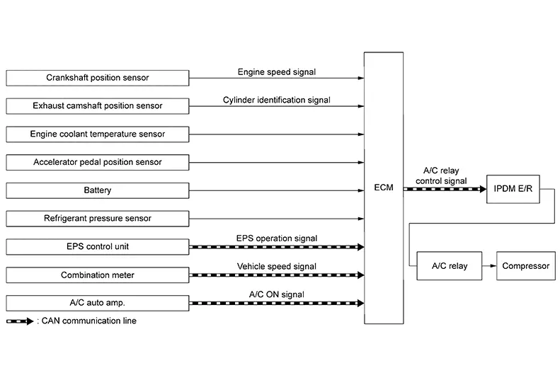
This system improves engine operation when the air conditioner is used.
Under the following conditions, the air compressor is turned off.
-
When the accelerator pedal is fully depressed (selector lever is in R position).
-
When cranking the engine.
-
At high engine speeds.
-
When the engine coolant temperature becomes excessively high.
-
When operating power steering during low engine speed or low Nissan Sentra vehicle speed.
-
When engine speed is excessively low.
-
When refrigerant pressure is excessively low or high.
Automatic Speed Control Device (ascd)
System Description
System Description
SYSTEM DIAGRAM
BASIC ASCD SYSTEM
CAUTION:
Always drive Nissan Sentra vehicle in safe manner according to traffic conditions and obey all traffic laws.
-
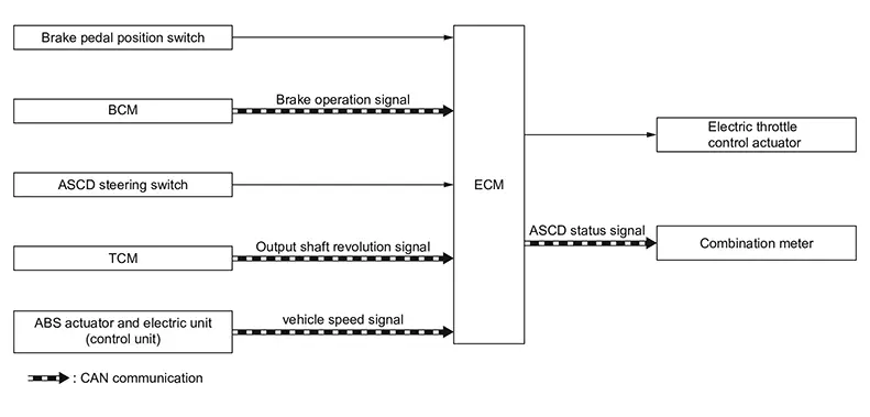
Automatic Speed Control Device (ASCD) allows a driver to keep Nissan Sentra vehicle at predetermined constant speed without depressing accelerator pedal by driverŌĆ▓s setting of vehicle speed*.
*: Driver can set the Nissan Sentra vehicle speed between approximately 40 km/h (25 MPH) and 144 km/h (89 MPH).
-
ECM transmits a ASCD operation status signal to the combination meter and operation status of ASCD is indicated on the information display in the combination meter. Refer to Operation.
-
If any malfunction occurs in ASCD system, it automatically deactivates control.
CANCEL OPERATION
-
When any of following conditions exist, cruise operation will be canceled.
-
ASCD switch is pressed (Set speed will be cleared)
-
CANCEL switch is pressed
-
More than 2 switches at ASCD steering switch are pressed at the same time (Set speed will be cleared)
-
Brake pedal is depressed
-
Clutch pedal is depressed or gear position is changed to neutral position (M/T models)
-
Selector lever is in N, P or R range (CVT models)
-
Nissan Sentra Vehicle speed decreased to 13 km/h (8 MPH) lower than the set speed
-
VDC system is operated
-
Actual Nissan Sentra vehicle speed decreased to approximately 30 km/h (18 MPH) or less
-
-
When the ECM detects any of the following conditions, the ECM will cancel the cruise operation and inform the driver by blinking ASCD indicator.
-
Engine coolant temperature is excessively higher than the normal operating temperature, ASCD indicator may blink slowly.
(When the engine coolant temperature decreases to the normal operating temperature, ASCD indicator will stop blinking and the cruise operation will be able to work by pressing COAST/SET switch or RESUME/ACCELERATE switch.)
-
Malfunction for some self-diagnoses regarding ASCD control
(When ASCD is operating, all of ASCD operations will be canceled and Nissan Sentra vehicle speed memory will be erased.)
-
Can Communication
System Description
System Description
CAN (Controller Area Network) is a serial communication line for real time application. It is an on-Nissan Sentra vehicle multiplex communication line with high data communication speed and excellent error detection ability. Many electronic control units are equipped onto a Nissan Sentra vehicle, and each control unit shares information and links with other control units during operation (not independent). In CAN communication, control units are connected with 2 communication lines (CAN H line, CAN L line) allowing a high rate of information transmission with less wiring.
Each control unit transmits/receives data but selectively reads required data only.
Refer to System Description, about CAN communication for detail.
Cooling Fan Control
System Description
System Description
SYSTEM DIAGRAM
 Note:
Note:
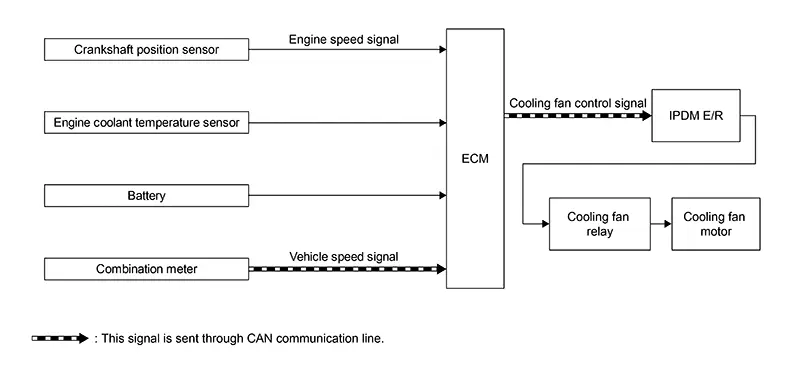
Cooling fan relay is changed to "Cooling fun module".
SYSTEM DESCRIPTION
ECM controls cooling fan speed corresponding to Nissan Sentra vehicle speed, engine coolant temperature, refrigerant pressure, air conditioner ON signal. Then control system has 3-step control [ HIGH/LOW/OFF ].
Cooling Fan Operation
ECM transmits a pulse duty (PWM) signal to IPDM E/R.
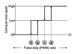
IPDM E/R has threshold value to the pulse duty (PWM) signal and operates cooling fan motor with three phases of [HI (high-speed) /LOW (low-speed) /OFF].
|
|
: ŌĆéLess than 30% (OFF ŌåÉ low-speed) |
|
|
: ŌĆéMore than 40% (OFF ŌåÆ low-speed) |
|
|
: ŌĆéLess than 50% (low-speed ŌåÉ high-speed) |
|
|
: ŌĆéMore than 60% (low-speed ŌåÆ high-speed) |


Cooling Fan Relay Operation
The ECM controls cooling fan relays in IPDM E/R through CAN communication line.
|
Cooling fan speed |
Cooling fan relay |
|
|---|---|---|
|
1 |
2 |
|
|
Stop (OFF) |
OFF |
OFF |
|
Low (LOW) |
ON |
OFF |
|
High (HI) |
OFF |
ON |
Dig (direct Injection Gasoline) System
System Description
System Description
SYSTEM DIAGRAM

SYSTEM DESCRIPTION
The adoption of the direct fuel injection system [DIG (Direct Injection Gasoline)] enables more accurate adjustment of fuel injection quantity by injecting atomized high-pressure fuel directly into the cylinder. This method allows high-powered engine, high torque, low fuel consumption, quietness, and emissions-reduction.
The amount of fuel injected from the fuel injector is determined by the ECM. The ECM controls the length of time the valve remains open (injection pulse duration). The amount of fuel injected is a program value in the ECM memory. The program value is preset by engine operating conditions. These conditions are determined by input signals (for engine speed and intake air and fuel rail pressure) from the crankshaft position sensor, camshaft position sensor, mass air flow sensor and the fuel rail pressure sensor.
FUEL INJECTION CONTROL
Injection Pattern
ECM conducts sequential injection (1 injection per 2 rotations of engine to each cylinder, suitable injection according to each cylinder's ignition order).
Injection when starting the engine
When starting the engine, ECM determines the amount of fuel injected according to conditions such as engine coolant temperature to make the starting smoother.
Also, conducts the starting control with stratified-charge combustion according to conditions.
Injection when driving normally
Normally, ECM determines the amount of injection to be an optimum air-fuel mixture ratio for homogeneous combustion.
Cut-in injection when acceleration
When accelerating, according to the opening speed of throttle valve, ECM conducts a cut-in injection adding to normal injection and improves accelerating performance.
DIRECT FUEL INJECTION CONTROL
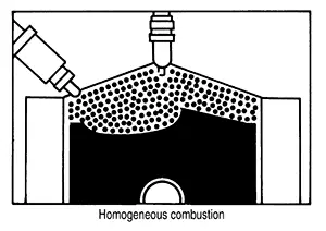
Homogeneous Combustion
Homogeneous combustion is a combustion method that fuel is injected during intake process so that combustion occurs in the entire combustion chamber, as is common with conventional methods. As for a start except for starts with the engine cold, homogeneous combustion occurs.
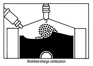
Stratified-charge Combustion
Stratified-charge combustion is a combustion method which enables extremely lean combustion by injecting fuel in the latter half of a compression process, collecting combustible air-fuel around the spark plug, and forming fuel-free airspace around the mixture. Right after a start with the engine cold, the catalyst warm-up is accelerated by stratified-charge combustion.
VARIOUS FUEL INJECTION INCREASE/DECREASE COMPENSATION
The amount of fuel injected is compensated to improve engine performance under various operating conditions as listed below.
<Fuel increase>
-
During warm-up
-
When starting the engine
-
During acceleration
-
Hot-engine operation
-
When selector lever position is changed from N to D
-
High-load, high-speed operation
<Fuel decrease>
-
During deceleration
-
During high engine speed operation
MIXTURE RATIO FEEDBACK CONTROL (CLOSED LOOP CONTROL)
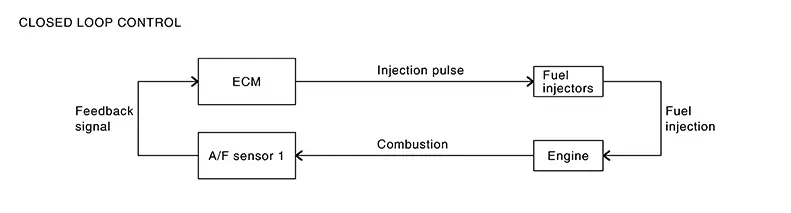
The mixture ratio feedback system provides the best air-fuel mixture ratio for driveability and emission control. The three way catalyst (manifold) can better reduce CO, HC and NOx emissions. This system uses A/F sensor 1 in the exhaust manifold to monitor whether the engine operation is rich or lean. The ECM adjusts theinjection pulse width according to the sensor voltage signal. And the correcting factor to control the pulse width is displayed as ŌĆ£A/F CORRECTIONŌĆØ, or ŌĆ£S-FUEL TRM-B1 [%]ŌĆØ. For more information about A/F sensor 1, Refer to Component Description. This maintains the mixture ratio within the range of stoichiometric (ideal air-fuel mixture). This stage is referred to as the closed loop control condition.
Heated oxygen sensor 2 is located downstream of the three way catalyst (manifold). Even if the switching characteristics of A/F sensor 1 shift, the air-fuel ratio is controlled to stoichiometric by the signal from heated oxygen sensor 2.
Open Loop Control
The open loop system condition refers to when the ECM detects any of the following conditions. Feedback control stops (clamp) in order to maintain stabilized fuel combustion.
-
Deceleration and acceleration
-
High-load, high-speed operation
-
Malfunction of A/F sensor 1 or its circuit
-
Insufficient activation of A/F sensor 1 at low engine coolant temperature
-
High engine coolant temperature
-
During warm-up
-
After shifting from N to D
-
When starting the engine
MIXTURE RATIO SELF-LEARNING CONTROL
The mixture ratio feedback control system monitors the mixture ratio signal transmitted from heated oxygen sensor 1. This feedback signal is then sent to the ECM. The ECM controls the basic mixture ratio as close to the theoretical mixture ratio as possible. However, the basic mixture ratio is not necessarily controlled as originally designed. Both manufacturing differences (i.e., mass air flow sensor hot wire) and characteristic changes during operation (i.e., fuel injector clogging) directly affect mixture ratio.
Accordingly, the difference between the basic and theoretical mixture ratios is monitored in this system.This is then computed in terms of ŌĆ£injection pulse durationŌĆØ to automatically compensate for the difference between the two ratios.
ŌĆ£Fuel trimŌĆØ refers to the feedback compensation value compared against the basic injection duration. Fuel trimincludes short term fuel trim and long term fuel trim.
ŌĆ£Short term fuel trimŌĆØ is the short-term fuel compensation used to maintain the mixture ratio at its theoretical value. The signal from heated oxygen sensor 1 indicates whether the mixture ratio is RICH or LEAN compared to the theoretical value. The signal then triggers a reduction in fuel volume if the mixture ratio is rich, and anincrease in fuel volume if it is lean.
ŌĆ£Long term fuel trimŌĆØ is overall fuel compensation carried out long-term to compensate for continual deviation of the short term fuel trim from the central value. Such deviation will occur due to individual engine differences,wear over time and changes in the usage environment.
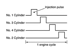
FUEL INJECTION TIMING
Fuel is injected into each cylinder during each engine cycle according to the ignition order.
STRATIFIED-CHARGE START CONTROL
The use of the stratified-charge combustion method enables emissions-reduction when starting with the engine cold.
FUEL SHUT-OFF
Fuel shut-off during deceleration
Fuel to each cylinder is cut off during deceleration for restraint of HC and improvement of fuel efficiency.
Engine speed at which fuel shut-off and recovery is conducted are programmed in detail according to various factors such as idle judgment, Nissan Sentra vehicle speed, gear position, engine coolant temperature etc. for optimizing emission and mileage performance.Also, no fuel shut-off is applied at extreme deceleration.
Fuel shut-off when the engine speed is excessively high
ECM shuts off fuel for all cylinders at the engine speed over 6,500 rpm, and recovers under 6,200 rpm.
Fuel shut-off when the engine speed is excessively high with no load
ECM shuts off fuel for all cylinders at the engine speed is high, and the Nissan Sentra vehicle speed is 0 km/h with N or P gear position for more than certain duration.
Fuel shut-off when the engine is over heating
ECM judges as the engine is over heating and conducts fuel shut-off when the output voltage of engine coolant temperature sensor exceeds the over heating judgment voltage for certain duration.
Also, malfunction indicator lamp (MIL) illuminates when the engine is judged as over heating.
And, once the engine over heating judgment is made, malfunction indicator lamp (MIL) remains ON even the engine coolant temperature becomes low (returns to normal), then fuel will be shut off at 2,000 rpm.
Fuel shut-off will be deactivated when the ignition key is turned OFF once, but malfunction indicator lamp (MIL) remains ON. The deactivation of malfunction indicator lamp (MIL) can be done by clearing self diagnosis results.
CAUTION:
Erase self diagnosis results only after the investigation of the engine over heating cause.
Fuel shut-off when N ŌåÆ D position is selected
Fuel shut-off is conducted when the engine speed is high and N ŌåÆ D position is selected.
Fuel shut-off when the engine stalls consecutively
To protect CVT, ECM conducts fuel shut-off when the engine speed is high despite the Nissan Sentra vehicle speed is excessively slow for more than several minutes with gear position except N or P. This control is not conducted when the malfunction of Nissan Sentra vehicle speed signal exists.
Fuel shut-off when malfunction indicator lamp (MIL) system is not working
ECM warns driver by conducting fuel shut-off when the request to illuminate malfunction indicator lamp (MIL) due to some of the self diagnosis relating electric throttle system or ECM continuously exist for more than 5 trips. ECM shuts off fuel at approx. 2,500 rpm and recovers at approx. 2,000 rpm.
Fuel shut-off when the throttle stuck to closed position
ECM conducts fuel shut-off when the electric throttle is stuck to its closed position.
But, for the sake of heating capability, ECM allows the engine start at N or P gear position with limited engine speed.
Eco Mode System
System Description
System Description
SYSTEM DIAGRAM
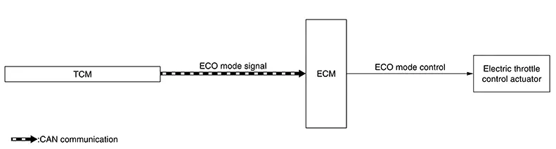
SYSTEM DISCRIPTION
-
ECM receives an ECO mode signal from TCM via CAN communication and improves the fuel economy by controlling the throttle movement to less than usual.
-
For the details of the ECO mode. Refer to System Description.
ECO Drive Navigator
ECM transmits an ECO drive navigator signal calculated from the accelerator pedal position and the Nissan Sentra vehicle speed to the combination meter via CAN communication.
When the acceleration guide is selected in ECO meter display switching function, the suitable accelerator position for fuel economy will be displayed. For display, Refer to System Description (TYPE A) or System Description (TYPE B).
FAIL-SAFE
If ECM detects a malfunction during ECO mode, the ECO mode indicator lamp turns OFF and the control switches to the normal mode control.
Egr System
System Description
System Description
SYSTEM DIAGRAM
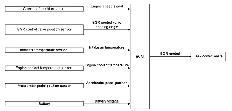
SYSTEM DESCRIPTION
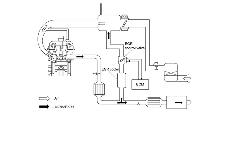
EGR system decreases oxygen density in intake air by recirculating a part of exhaust gas to intake system, and decreases recirculating exhaust gas temperature by water cooling type cooler. This is to reduce combustion temperature inside of cylinder so that control generating NOx and knocking. Also this function is for coexistence of driveability and the exhaust performance, and fuel economy.
EGR is deactivated under the following conditions to enhance driveability:
-
Engine starting
-
Engine at idle
-
Low engine coolant temperature
-
High engine coolant temperature
-
High engine speed
-
Low intake air temperature
-
Low battery voltage
Electric Ignition System
System Description
System Description
SYSTEM DIAGRAM

SYSTEM DESCRIPTION
Ignition order: 1 - 3 - 4 - 2
The ignition timing is controlled by the ECM to maintain the best air-fuel ratio for every running condition of the engine. The ignition timing data is stored in the ECM. The ECM receives information such as the injection pulse width and camshaft position sensor signal. Computing this information, ignition signals are transmitted to the power transistor.
During the following conditions, the ignition timing is revised by the ECM according to the other data stored in the ECM.
-
At starting
-
During warm-up
-
At idle
-
At low battery voltage
-
During acceleration
The basic ignition timing is programmed within the anti-knocking zone, if recommended fuel is used under dry conditions. The knock sensor feedback control does not operate under normal driving conditions. If engine knocking occurs, the knock sensor monitors the condition. The signal is transmitted to the ECM. The ECM retards the ignition timing to eliminate the knocking condition.
BASIC CONTROL
-
When starting, ECM controls ignition timing according to the engine speed and coolant temperature.
-
After the engine is started, ECM corrects the ignition timing according to the driving conditions (engine coolant temperature, accelerator pedal position, throttle position, control request from CVT etc.) based on the engine speed and fuel injection pulse width.
-
If knocking occurs, ECM retards the ignition timing within the anti-knocking control zone according to the knocking condition.
-
When the engine is idling, ECM controls the ignition timing to stabilize idling speed.
-
ECM controls the duration of power transmission (power transistor ON time) to ignition coil according to the engine speed and battery voltage.
-
When the engine idle speed or the ignition timing deviates from specified value, "Idle Air Volume Learning" is required.
CYLINDER DISTINCTION CONTROL
ECM distinguishes cylinder based on the combination of signals of crankshaft position sensor, intake camshaft position sensor and exhaust camshaft position sensor, and if any of sensor malfunctions distinguishes cylinder with normal sensors.
|
Abnormal point |
Sensor to use for cylinder distinction |
|---|---|
|
Crankshaft position sensor |
Exhaust camshaft position sensor |
|
Intake camshaft position sensor |
|
|
Exhaust camshaft position sensor |
|
Engine Protection Control at Low Engine Oil Pressure
System Description
System Description
SYSTEM DIAGRAM
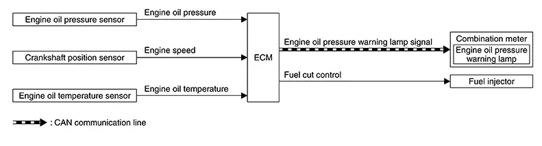
SYSTEM DESCRIPTION
-
The engine protection control at low engine oil pressure warns the driver of a decrease in engine oil pressure by the engine oil pressure warning lamp before the engine becomes damaged.
-
When detecting a decrease in engine oil pressure at an engine speed less than 1,000 rpm, ECM transmits an engine oil pressure warning lamp signal to the combination meter.The combination meter turns ON the engine oil pressure warning lamp, according to the signal.
-
When detecting a decrease in engine oil pressure at an engine speed 1,000 rpm or more, ECM transmits an engine oil pressure warning lamp signal to the combination meter. When detecting a decrease in engine oil pressure, ECM cuts fuel if the engine speed exceeds the specified value. Refer to Fail-safe.
Decrease in engine oil pressure
Engine speed
Combination meter
Fuel cut
Engine oil pressure warning lamp
Detection
Less than 1,000 rpm
ON*
NO
1,000 rpm or more
ON
YES
*: When detecting a normal engine oil pressure, ECM turns OFF the engine oil pressure warning lamp.
Engine Warning
System Description
System Description
DESIGN/PURPOSE
Warn the driver that the state of the engine.
|
Symbol |
Message |
|---|---|

|
|
BULB CHECK
Not applicable
OPERATION AT COMBINATION METER CAN COMMUNICATION CUT-OFF OR UNUSUAL SIGNAL
For the operation for CAN communications blackout or abnormal signal reception.
SYSTEM DIAGRAM
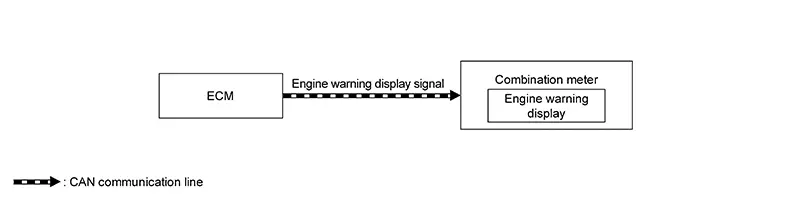
SIGNAL PATH
ECM transmits the engine warning display signal to combination meter via CAN communication.
Then the engine warning displays.
LIGHTING CONDITION
When all of the following conditions is satisfied:
-
Ignition switch: ON
-
Failure of powertrain which may cause serious accident is detected.
-
Driving condition may cause accident or situation that car cannot run.
SHUTOFF CONDITION
When any of the following conditions is satisfied:
-
Ignition switch: OFF
-
Failure of powertrain which may cause serious accident is not detected.
-
No problem about driving condition.
TIMING CHART
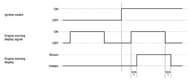
|
t |
: 100 ms |
Evaporative Emission System
System Description
System Description
SYSTEM DIAGRAM
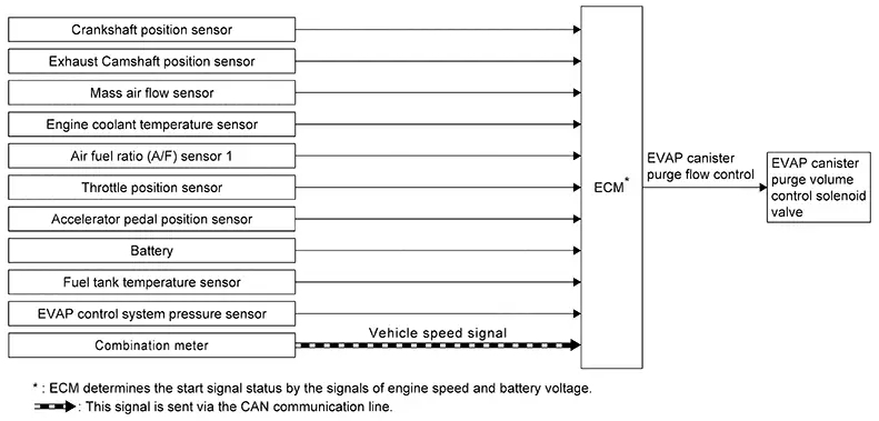
SYSTEM DESCRIPTION
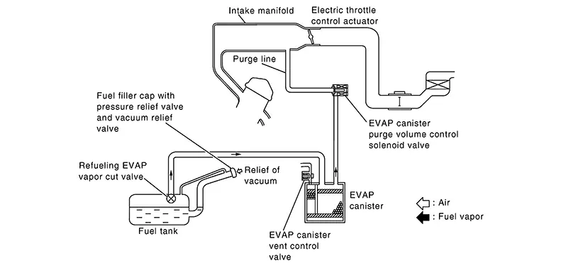
The evaporative emission system is used to reduce hydrocarbons emitted into the atmosphere from the fuel system. This reduction of hydrocarbons is accomplished by activated charcoals in the EVAP canister.
The fuel vapor in the sealed fuel tank is led into the EVAP canister which contains activated carbon and the vapor is stored there when the engine is not operating or when refueling to the fuel tank.
The vapor in the EVAP canister is purged by the air through the purge line to the intake manifold when the engine is operating. EVAP canister purge volume control solenoid valve is controlled by ECM. When the engine operates, the flow rate of vapor controlled by EVAP canister purge volume control solenoid valve is proportionally regulated as the air flow increases.
EVAP canister purge volume control solenoid valve also shuts off the vapor purge line during decelerating and idling.
Exhaust Valve Timing Control
System Description
System Description
SYSTEM DIAGRAM
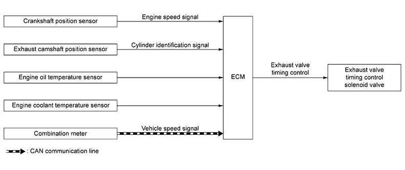
SYSTEM DESCRIPTION
With the exhaust valve timing controller which controls the phase of exhaust camshaft to optional position continuously, ECM improves both low-middle speed torque and high speed performance, emission and fuel efficiency by optimizing the exhaust valve open/close timing according to driving conditions.
The exhaust valve timing controller is hydraulically controlled by the exhaust valve timing control solenoid valve.
This mechanism hydraulically controls cam phases continuously with the fixed operating angle of the exhaust valve.
The ECM receives signals such as crankshaft position, camshaft position, engine speed, and engine oil temperature. Then, the ECM sends ON/OFF pulse duty signals to the exhaust valve timing control solenoid valve depending on driving status. This makes it possible to control the shut/open timing of the exhaust valve to increase engine torque and output in a range of high engine speed.
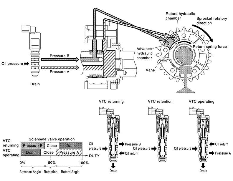
EXHAUST VALVE TIMING CONTROL SOLENOID VALVE CONTROL
The exhaust valve timing control solenoid valve is driven ON-OFF (duty control) by ECM output signal, and controls the open/close timing of the exhaust valve to the optimum by changing its duty ratio according to the Nissan Sentra vehicle's driving condition.
|
Exhaust valve timing control solenoid valve condition |
Exhaust valve timing controller operation |
|---|---|
|
Engine OFF |
When starting the engine, the controller vane and sprocket are fixed in full advanced position by the reaction force of return spring, improving the starting performance of the engine. |
|
Active (Retard angle) |
When the energization rate to the control solenoid valve is increased, the oil pressure from the oil pump is conveyed to the retard angle chamber of the controller. And advanced angle chamber oil is drained. Accordingly, the controller vane rotates leftward and the phase of camshaft becomes retard angle.This condition brings about the greater overlap with the intake valve, enabling the exhaust gas cleaning by the internal EGR effect and the fuel consumption improvement by the reduction in pumping loss. |
|
Neutral (Maintained) |
When it is the target valve timing, the energization rate to the control solenoid valve is adjusted to the intermediate state. The solenoid valve is positioned at the neutral position and the oil path is interrupted to maintain the cam shaft phase. |
|
Return (Advanced angle) |
When the energization rate to the control solenoid valve is decreased, the oil pressure from the oil pump is conveyed to the advanced chamber of the controller. And retard angle chamber oil is drained.Accordingly, the controller vane rotates rightward and the phase of camshaft becomes advanced angle. |
EXHAUST VALVE TIMING CONTROL FEEDBACK CONTROL
Cam Position Detection
The camshaft position sensor mounted at the rear of the cylinder head detects a cam position, by using thegroove on the plate located at the rear of the exhaust camshaft.
Feedback Control
The camshaft position sensor feeds back an actual cam position signal to ECM. Based on the signal, ECM controls the exhaust valve timing control solenoid valve to satisfy the optimum target valve opening/closing timing according to a driving condition.
Fuel Filler Cap Warning System
System Description
System Description
SYSTEM DIAGRAM
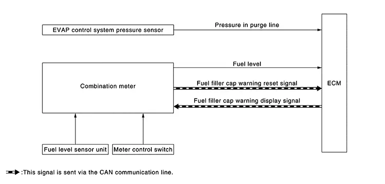
SYSTEM DESCRIPTION
The fuel filler cap warning system alerts the driver to the prevention of the fuel filler being left uncapped and malfunction occurrences after refueling, by turning ON the fuel filler cap warning display on the combination meter.
ECM judges a refueled state, based on a fuel level signal transmitted from the combination meter.
When a very small leak is detected through the EVAP leak diagnosis performed after judging the refueled state, ECM transmits a fuel filler cap warning display signal (request for display ON) to the combination meter via CAN communication.
When receiving the signal, the combination meter turns ON the fuel filler cap warning display.
CAUTION:
Check fuel filler cap installation condition when the fuel filler cap warning display turns ON.
Reset Operation
The fuel filler cap warning lamp tunes OFF, according to any condition listed below:
-
Reset operation is performed by long pressing operation of the OK switch on the steering wheel.
-
When the reset operation is performed, the combination meter transmits a fuel filler cap warning reset signal to ECM via CAN communication. ECM transmits a fuel filler cap warning display signal (request for display OFF) to the combination meter via CAN communication. When receiving the signal, the combination meter turns OFF the fuel filler cap warning display.
-
-
EVAP leak diagnosis result is normal.
-
Fuel refilled.
-
DTC erased by using CONSULT.
MIL turns ON if a malfunction is detected in leak diagnosis results again at the trip after the fuel filler cap warning display turns ON/OFF.
Fuel Pressure Control
System Description
System Description
SYSTEM DIAGRAM
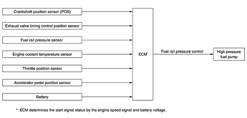
SYSTEM DESCRIPTION
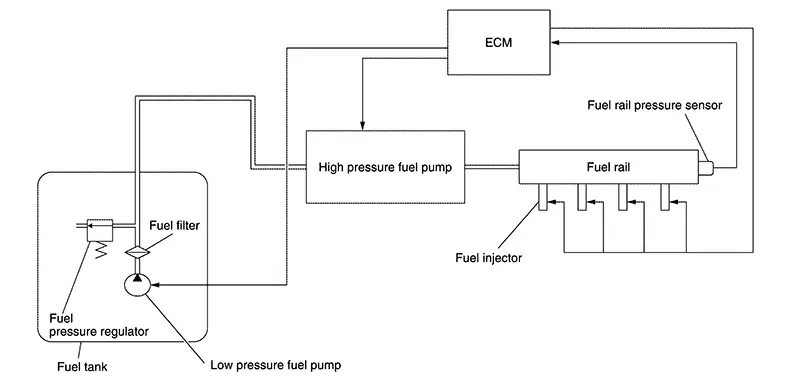
Low fuel pressure control
-
The low fuel pressure pump is controlled by ECM and pumps fuel according to a driving condition. The pumped fuel passes through the fuel filter and is sent to the high pressure fuel pump.
-
Low fuel pressure is adjusted by the fuel pressure regulator.
High fuel pressure control
-
The high pressure fuel pump is actuated by the cam of camshaft (EXH).
-
The high pressure fuel pump activates the high pressure fuel pump solenoid based on a signal received from ECM, and adjusts the amount of discharge by changing the timing of closing the inlet checkvalve to control fuel rail pressure.
For details about operation, Refer to Component Description.
Idle Speed Control
System Description
System Description
SYSTEM DESCRIPTION
ECM conducts feedback control of the engine idle speed to the target value, by controlling intake air volume with electric throttle, according to driving conditions such as engine warm-up condition, A/C loads, electric loads, etc.
IDLE SPEED FEEDBACK
ECM determines control target value based on the engine coolant temperature, A/C operation status, gear position, etc., then conducts feedback control to match the target value when idle judgment is made with transmission range switch signal ON, or when the Nissan Sentra vehicle speed is very low.
Also, adjustment of the engine idle speed is conducted by ECM's self learning (IDLE AIR VOLUME LEARNING).
CORRECTION OF BATTERY VOLTAGE
When battery voltage becomes lower than specified value, ECM corrects the target value to improve battery charging.
OTHER CORRECTIVE CONTROLS
-
When some electric load (power steering load, electric load, etc.) is turned ON, ECM controls target engine speed for each load accordingly.
-
When gear position is selected (NŌåÆD, DŌåÆN), ECM controls the engine speed by optimizing throttle opening to minimize shift shock.
-
When deceleration (accelerator pedal ONŌåÆOFF), ECM controls the engine speed by optimizing throttle opening to minimize shift shock and exhaust gas emission.
Information Display (combination Meter)
System Description
System Description
|
Item |
Symbol |
Function |
|---|---|---|
|
ASCD indicator |
 |
For detail of ASCD function, Refer to System Description. |
|
Message: - - Km/h / - - MPH |
||
|
Fuel filler cap warning |
 |
For detail of fuel filler cap warning system, Refer to System Description. |
|
Message: Loose Fuel Cap |
Intake Manifold Runner Control
System Description
System Description
SYSTEM DIAGRAM

SYSTEM DESCRIPTION
The intake manifold runner control valve installed at intake manifold generates tumble flow (vertical revolving flow) in combustion chamber, and by that effect air-fuel mixture is homogenized so that stabilizes combustion. The intake manifold runner control valve is driven by DC motor and controlled by ECM.
IDLING, LOW SPEED┬ĘSMALL LOAD RANGE
With intake manifold runner control valve closed the flowing field of tumble flow (vertical revolving flow) is generated by increased flow speed of gas and improves combustion so that enables stable combustion.
MIDDLE┬ĘHIGH SPEED RANGE
Intake resistance is reduced by opening (intake manifold runner control valve). This provide high intake efficiency so that output increases.
OPERATION OF INTAKE MANIFOLD RUNNER CONTROL VALVE
|
Valve position |
operating condition |
|---|---|
|
Valve closed 
|
Idling, low ┬Ęsmall load range |
|
Valve opened 
|
Other than above |
Intake Valve Timing Control
System Description
System Description
SYSTEM DIAGRAM
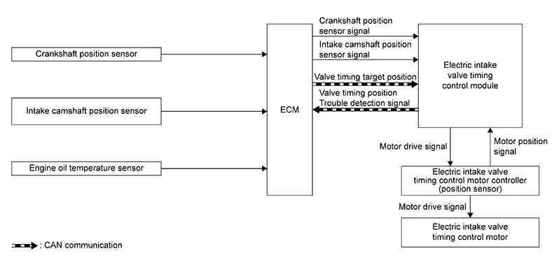
SYSTEM DESCRIPTION
Electric VTC responds faster than hydraulic VTC and can extend the operation angle of the camshaft. This improves the fuel economy, engine output, and exhaust performance.
This mechanism continuously controls the phase of camshaft by the electric intake valve timing (IVT) control motor with the amount of intake valve operation held constant.
ECM transmits a target position of the electric IVT control motor to electric IVT control module via CAN communication.
The electric IVT control module controls the electric IVT control motor according to a signal from ECM and changes the opening and closing timing of intake valve.
Furthermore, the electric IVT control module has a diagnostic function and transmits a DTC detection signal to ECM via engine communication when detecting a system error.
|
Intake camshaft condition |
Electric intake valve timing control actuator operation |
|---|---|
|
Advanced angle |
The electric intake valve timing control motor rotates the intake camshaft to advanced angle. |
|
Maintained |
Stop rotating the electric intake valve timing control motor to keep the intake camshaft position (cam phase). |
|
Retard angle |
The electric intake valve timing control motor rotates the intake camshaft to retard angle. |
Integrated Control of Engine, Cvt, and Abs
System Description
System Description
Real time communications (signal exchange) among control units (e.g. ECM, CVT, ABS, and combination meter) via CAN communication optimizes engine torque and lock-up during gear shift and prevents engine speed from decreasing during deceleration.
On Board Refueling Vapor Recovery (orvr)
Structure and Operation
Structure and Operation
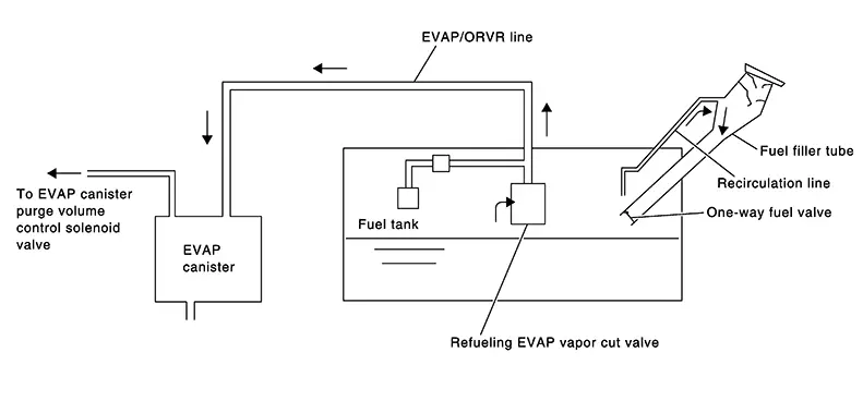
From the beginning of refueling, the air and vapor inside the fuel tank go through refueling EVAP vapor cut valve and EVAP/ORVR line to the EVAP canister. The vapor is absorbed by the EVAP canister and the air is released to the atmosphere.
When the refueling has reached the full level of the fuel tank, the refueling EVAP vapor cut valve is closed and refueling is stopped because of auto shut-off. The vapor which was absorbed by the EVAP canister is purged during driving.
Warning:
When conducting inspections below, be sure to observe the following:
-
Put a ŌĆ£CAUTION: FLAMMABLEŌĆØ sign in workshop.
-
Do not smoke while servicing fuel system. Keep open flames and sparks away from work area.
-
Be sure to furnish the workshop with a CO2 fire extinguisher.
CAUTION:
-
Before removing fuel line parts, carry out the following procedures:
-
Put drained fuel in an explosion-proof container and put lid on securely.
-
Release fuel pressure from fuel line. Refer to Work Procedure.
-
Disconnect battery ground cable.
-
-
Always replace O-ring when the fuel gauge retainer is removed.
-
Do not kink or twist hose and tube when they are installed.
-
Do not tighten hose and clamps excessively to avoid damaging hoses.
-
After installation, run engine and check for fuel leaks at connection.
-
Do not attempt to top off the fuel tank after the fuel pump nozzle shuts off automatically.
Continued refueling may cause fuel overflow, resulting in fuel spray and possibly a fire.
Power Generation Voltage Variable Control System
System Description
System Description
DESCRIPTION
ECM transmits a target power generation voltage signal received from IPDM E/R to the generator via LIN communication.
The generator includes a self-diagnosis function and transmits a diagnosis signal to ECM via LIN communication when detecting a malfunction. When ECM receives a diagnosis signal, ECM detects DTC and transmits a charge warning lamp request signal to the combination meter to turn ON the charge warning lamp.
Idle Start/stop System
System Description
System Description
SYSTEM DIAGRAM

INPUT/OUTPUT SIGNAL CHART
|
Input/Output |
Transmits/Receives component |
Signal name |
Description |
|
|---|---|---|---|---|
|
Input |
Accelerator pedal position sensor |
Accelerator pedal position sensor signal |
Detects an accelerator pedal position. |
|
|
Crankshaft position sensor |
Crankshaft position sensor signal |
Detects an engine speed. |
||
|
Engine coolant temperature sensor |
Engine coolant temperature sensor signal |
Detects an engine coolant temperature. |
||
|
Atmospheric pressure sensor |
Atmospheric pressure sensor signal |
Detects an atmospheric pressure. |
||
|
IPDM E/R |
CAN communication |
Start/Stop permit signal |
Detects the Electric Energy management system is ready to operate the idle start/stop system. |
|
|
Hood switch signal |
Detects engine hood status. |
|||
|
Starter status signal |
Detects the status of starter |
|||
|
Starter relay and starter control relay status signal |
Detects the status of Starter relay. |
|||
|
BCM |
CAN communication |
Stop lamp switch signal |
Detects the status of brake pedal switch. |
|
|
Door switch signal |
Detects the status of driver side door. |
|||
|
Start/Stop OFF switch signal |
Detects start/stop OFF switch status. |
|||
|
I-key exist information signal |
Detects the i-key exist |
|||
|
Driver seatbelt switch malfunction signal |
Detects the driver seatbelt switch is malfunction. |
|||
|
Delivery mode signal |
Detects Nissan Sentra vehicle is in delivery mode |
|||
|
Seat belt buckle switch signal |
Detects driver is sitting on the driver seat. |
|||
|
ABS actuator and electric unit (control unit) |
CAN communication |
Nissan Sentra Vehicle speed signal |
Detects Nissan Sentra vehicle speed. |
|
|
Brake fluid pressure sensor signal |
Detects brake fluid pressure. |
|||
|
ABS operation signal |
Detects ABS operation. |
|||
|
Start/Stop permit signal |
Detects the Braking system is ready to operate the idle start/stop system |
|||
|
ABS malfunction signal |
Detects ABS is malfunction |
|||
|
Brake booster pressure status signal |
Detects the status of brake booster pressure. |
|||
|
EPS control unit |
CAN communication |
EPS torque signal |
Detects an operational state of EPS system. |
|
|
A/C auto amp. |
CAN communication |
Start/Stop permit signal |
Detects the air conditioning system is ready to operate the idle start/stop system. |
|
|
Combination meter |
CAN communication |
Parking brake status signal |
Detects the status of parking brake |
|
|
TCM |
CAN communication |
Start/Stop permit signal |
Detects the transmission is ready to operate the idle start/stop system. |
|
|
Shift position signal |
Detects the transmission is ready to operate the idle start/stop system. |
|||
|
Transmission malfunction signal |
Detects Transmission is malfunction. |
|||
|
Chassis control module |
CAN communication |
Drive mode status signal |
Detects the drive mode status. |
|
|
Output |
BCM |
CAN communication |
Start/Stop status signal |
Transmits a start/stop status signal |
|
ST Cut relay ON request signal |
Transmits ST Cut relay ON request according to the start/stop system |
|||
|
Start/Stop switch lamp ON request signal |
Transmits the start/stop switch lamp ON request |
|||
|
ABS actuator and electric unit (control unit) |
CAN communication |
Start/Stop status signal |
Transmits a start/stop status signal |
|
|
Brake hold request signal |
Transmits the brake hold/release request according to the idle start/stop system. |
|||
|
EPS control unit |
CAN communication |
Start/Stop status signal |
Transmits a start/stop status signal |
|
|
A/C auto amp. |
CAN communication |
Start/Stop status signal |
Transmits a start/stop status signal |
|
|
TCM |
CAN communication |
Start/Stop status signal |
Transmits a start/stop status signal |
|
|
Combination meter |
CAN communication |
Start/Stop indicator lamp and message request signal |
Transmits request signal which turns ON the start/stop indicator lamp and display message |
|
SYSTEM DESCRIPTION
The idle start/stop system enables the engine to automatically stop/restart with a simple operation and reduces unnecessary idling during stoplight or traffic congestion to improve fuel economy, reduce exhaust gas, and minimize noise.
ECM detects a Nissan Sentra vehicle condition, engine condition and driverŌĆ▓s operation condition based on signals sent from each unit and the sensors to comprehensively control the idle start/stop system.
The operation condition of the idle start/stop system is indicated by the start/stop indicator lamp on the combination meter and showing on the information display. (Refer to Switch Name and Function.) If a malfunction is detected in the idle start/stop system, the system control is automatically deactivated and the malfunction is alerted to the driver by blinking the start/stop indicator lamp and showing the status on the information display. When a driverŌĆ▓s operation is judged as dangerous one during the idle start/stop system operation, the start/stop indicator lamp blinks at a high speed and the status is shown on the information display . The buzzer mounted on the combination meter sounds simultaneously to warn the driver of the dangerous operation.
Start/Stop indicator lamp status
|
System condition |
Condition |
Start/Stop indicator lamp |
Warning chime |
|---|---|---|---|
|
Operate |
Normal |
Illuminate |
ŌĆö |
|
Hood open |
Illuminate |
Sound |
|
|
Normal operation: Idle start/stop system inhibited state |
System conditions excluded failure are not satisfied. (Battery state of charge, A/C steering operation, driverŌĆ▓s seat belt is unbuckled etc) |
 |
ŌĆö |
|
Fail-Safe |
Malfunction of idle start/stop system |
Blinking |
ŌĆö |
Starting the engine from idle start/stop system operation is regarded as ŌĆ£RestartŌĆØ.
BASIC OPERATION
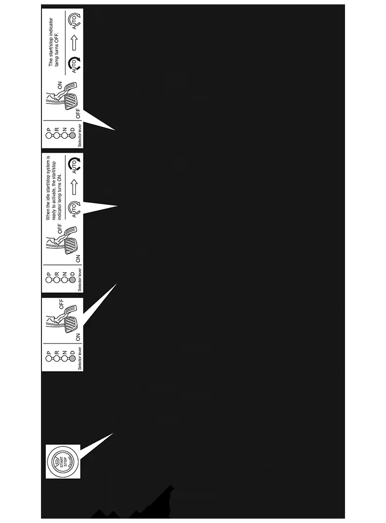
FUNCTION DESCRIPTION
When the idle start/stop system readiness conditions are satisfied while the Nissan Sentra vehicle is moving, the system is ready.
When the idle start/stop system operation conditions are satisfied while the Nissan Sentra vehicle is in a stop condition, the engine is stopped.
In addition, the AT electric oil pump is activated to supply oil pressure to the clutch and the pulley.
The amount of fuel saved by the idle start/stop system are indicated on the combination meter.
When the engine restart conditions are satisfied, ECM makes IPDM E/R restart the engine.
After restarting the engine, the start/stop indicator lamp and the indication on the information display turn OFF.
Start/Stop Readiness Condition
ECM judges idle start/stop system is ready when the following conditions are satisfied.
|
Item |
Condition |
||
|---|---|---|---|
|
Nissan Sentra Vehicle |
Start/Stop OFF switch |
OFF (Switch indicator: OFF) |
|
|
Start/Stop indicator Lamp |
Not blink (No malfunction) |
||
|
Door (driver side) |
Close |
||
|
Seat belt (driver side) |
Fastened |
||
|
Driving history |
Drive the Nissan Sentra vehicle at 13 km/h (8 MPH) or more after start the engine with ignition switch |
||
|
Drive the Nissan Sentra vehicle at 8 km/h (5 MPH) or more after restart Note:
When shift the selector lever R to D, drive the Nissan Sentra vehicle at 10 km/h (6.3 MPH) or more. |
|||
|
Passes 5 seconds or more after restart |
|||
|
Hood |
Close |
||
|
Air conditioning |
Automatic air conditioning |
Not in DEF mode |
|
|
Receives Start/Stop permit signal |
|||
|
Manual air conditioning |
Not in DEF mode |
||
|
ABS |
System is normal |
||
|
ABS not activated*2 |
|||
|
Receives Start/Stop permit signal |
|||
|
EPS |
System is normal |
||
|
Battery status |
Receives Start/Stop permit signal from IPDM E/R. |
||
|
Gear Position |
D position |
||
|
I-key |
I-key exists inside Nissan Sentra vehicle |
||
|
ST RLY operation status |
Relay operates correctly |
||
|
Starter motor |
No starter motor long continuous operation |
||
|
Delivery mode |
Not in delivery mode*2 |
||
|
Brake booster pressure |
Presence of sufficient negative pressure to a brake force. (Refer to System Description.) |
||
|
Elevation |
2,500 m or less |
||
|
Engine |
MIL (Malfunction indicator lamp) |
Not Illuminate (No malfunction) |
|
|
Engine coolant temperature |
36 - 100 Ōäā (96.8 - 212┬░F) |
||
*1: If ABS system is activated, drive the Nissan Sentra vehicle at 12 km/h (7.5 MPH) or more after stop the vehicle.
*2: No activation in market
CAUTION:
-
The idle start/stop system may be cancelled when the battery is weak or if a battery other than the idle start/stop system specific battery is used.
-
Even though the Nissan Sentra vehicle is in above conditions, the idle start/stop system may be cancelled automatically.
Start/Stop Operation Condition
When the following conditions are satisfied, ECM stops the engine. And the combination meter turns ON a start/stop indicator lamp.
|
Item |
Condition |
|
|---|---|---|
|
Nissan Sentra Vehicle |
Vehicle speed |
Nissan Sentra Vehicle stopped [0 km/h (0 MPH)] |
|
Steering wheel |
Not steer (steering force does not occur) or when the steering wheel angle is less than 45 deg for both direction. |
|
|
Brake pedal |
Depressed |
|
|
Brake fluid pressure |
0.8 Mpa (8 bar, 8.2 kg/cm2, 116 psi) |
|
|
Nissan Sentra Vehicle angularity |
Approx. 14% or less |
|
|
ST RLY Cut relay |
Close |
|
|
Brake booster pressure |
Presence of sufficient negative pressure to a brake force. (Refer to System Description.) |
|
|
Engine |
Engine speed |
Around idle speed (Approx. 1,150 rpm or less) |
|
Elevation |
2500 m (8,202 ft) |
|
|
Engine coolant temperature |
36 - 100Ōäā (96.8 - 212┬░F) |
|
|
Engine system |
Permit Start/Stop operation |
|
|
Transmission |
Transmission system |
Receives Start/Stop permit signal |
|
Gear position |
D position. |
|
Restart Condition
When any of the following conditions is satisfied during idle start/stop system operating condition, ECM restarts the engine. And the combination meter turns OFF the start/stop indicator lamp.
|
Item |
Condition |
||
|---|---|---|---|
|
Start/Stop |
|||
|
Nissan Sentra Vehicle |
Start/Stop OFF switch |
ON (Switch indicator ON) |
|
|
Door (driver side) |
Open |
||
|
Seat belt |
Released |
||
|
I-key |
I-key doesn't exist inside Nissan Sentra vehicle |
||
|
Steering wheel |
Steered (Steering force occurs) or when the steering wheel angle is more than 45 deg for both direction. |
||
|
Air conditioning |
Auto air conditioning |
Select DEF mode |
|
|
Air conditioning system cannot keep the performance. |
|||
|
Manual air conditioning |
Select DEF mode and fan is ON |
||
|
Brake |
Brake pedal |
Released |
|
|
Brake pedal negative pressure |
Insufficient brake negative pressure |
||
|
Accelerator pedal |
Depressed |
||
|
Engine |
Engine coolant temperature |
less than 36Ōäā (96.8┬░F)ŃĆü over than 100Ōäā (212┬░F) |
|
|
Engine system |
Inhibit Start/Stop operation |
||
|
Trans mission |
Shift lever position |
Except for D position |
|
|
Battery |
Poor battery performance (for details, refer to System Description.) |
||
|
ABS |
Receives Start/Stop operation |
||
|
Intelligent Parking Assist |
|||
Engine stalled Condition
When any of the following conditions is satisfied during idle start/stop system operating condition, ECM stalls the engine.
|
Item |
Condition |
|
|---|---|---|
|
Nissan Sentra Vehicle |
Hood |
Open |
-
The engine may restart automatically if required by the idle start/stop system.
-
Place the Ignition switch in the "OFF" position before opening the hood or performing any maintenance. Failure to do so may result in serious injuries due to automatic engine restart.
-
Always place the Ignition switch in the "OFF" position before leaving your vehi-cle, as the system may have turned the engine off, but the Ignition will still be on and automatic restart may occur.
Warning Lamps/indicator Lamps
Start/stop Indicator Lamp
Start/Stop Indicator Lamp
DESIGN/PURPOSE
The start/stop indicator lamp informs the driver of the status of the idle start/stop system.
-
Turns ON while the idle start/stop system is operating.
-
Blinks when a malfunction related to the idle start/stop system is detected after engine start.
BULB CHECK
Not applicable
SYNCHRONIZATION WITH WARNING CHIME
Applicable
For warning chime, Refer to System Description(TYPE A) or System Description(TYPE B).
OPERATION AT COMBINATION METER CAN COMMUNICATION CUT-OFF OR UNUSUAL SIGNAL
For the operation for CAN communication blackout in the combination meter, Refer toFail-Safe(TYPE A) or Fail-Safe(TYPE B).
SYSTEM DIAGRAM
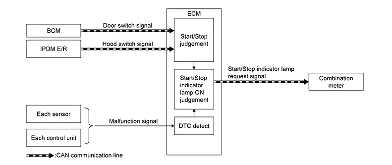
SIGNAL PATH
-
ECM transmits a start/stop indicator lamp request signal to the combination meter via CAN communication when the idle start/stop system operation is permitted or a malfunction is detected.
-
The combination meter turns ON or blinks the start/stop indicator lamp according to a signal transmitted from ECM.
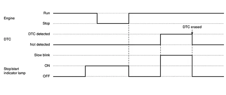
LIGHTING CONDITION
-
During idle start/stop system operation.
-
DTC is detected. (Blinking.)
Note:
When the hood is opened, the idle start/stop system is cancelled and the engine cannot be restarted automatically. Accordingly, the engine needs to be started with the ignition key.
For details, Refer to System Description(TYPE A) or System Description(TYPE B).
SHUTOFF CONDITION
-
The operation permit conditions of the idle start/stop system are not satisfied.
-
After an engine restart.
-
After erasing DTC.
TIMING CHART
Warning/indicator/chime List
Warning Lamp/indicator Lamp
Warning Lamp/Indicator Lamp
Note:
Regarding the arrangement. Refer to Design(TYPE A) or Design(TYPE B).
|
Item |
Design |
Reference |
|---|---|---|
|
Engine Oil Pressure Warning Lamp |
|
Regarding the function. Refer to System Description(TYPE A) or System Description(TYPE B). |
|
Malfunction indicator lamp (MIL) |
|
Regarding the function. System Description |
|
Start/Stop indicator lamp |
|
Regarding the function. Refer to Start/Stop Indicator Lamp |


Warning/indicator (on Information Display)
Warning/Indicator (On Information Display)
|
Item |
Reference |
|---|---|
|
ASCD indicator |
Operation |
|
Fuel filter cap warning |
System Description |
|
Start/Stop indicator |
Switch Name and Function |
Warning Chime
Warning Chime
|
Item |
Reference |
|---|---|
|
Start/Stop warning |
System Description |
Other materials:
Ecu Diagnosis Information. Abs Actuator and Electric Unit (control Unit)
Abs Actuator and Electric Unit (control Unit)
Values on the Diagnosis Tool
Values on the
Diagnosis Tool
Note:
The following table includes information (items)
inapplicable to this Nissan Sentra vehicle: For information (items) applicable to
this vehicle, refer to CONSULT display ...
INSTALLATION. Sonar Buzzer. Removal and Installation
CAUTION:
Verify that the connector direction is within the
specification shown when assembling the bumper fascia.
(A)
: Horizontal position
(a)
...
System Settings Cannot Be Turned On/off
Diagnosis Procedure
Diagnosis Procedure
CHECK SYSTEM SETTING
Turn ignition switch ON.
Check that the each system settings is
selectable on the combination meter.
Is the inspection result norma ...