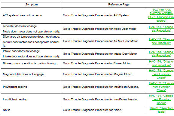
Nissan Sentra Service Manual: Symptom diagnosis
HEATER AND AIR CONDITIONING SYSTEM CONTROL SYMPTOMS
Symptom Table
INSUFFICIENT COOLING
Component Function Check
Symptom: insufficient cooling
Inspection flow
1. Confirm symptom by performing operation check - temperature decrease
- Press the a/c switch.
- Turn temperature control dial counterclockwise to maximum cold.
- Check for cold air at discharge air outlets.
Can a symptom be duplicated? YES >> GO TO 3 NO >> GO TO 2
2. Check for any symptoms
Perform a complete operational check and check for any symptoms. Refer to HAC-157, "Work Procedure".
Does another symptom exist? YES >> Refer to HAC-181, "Symptom Table".
NO >> System OK.
3. Check for service bulletins
Check for any service bulletins.
>> GO TO 4
4. Check drive belts
Check a/c compressor belt tension. Refer to em-16, "inspection".
Is the inspection result normal? Yes >> go to 5 no >> adjust or replace compressor belt. Refer to em-16, "adjustment".
5. Check air mix door motor operation
Check and verify air mix door mechanism for smooth operation.
Does air mix door operate correctly? Yes >> go to 6 no >> check air mix door motor circuit. Refer to hac-163, "diagnosis procedure".
6. Check cooling fan motor operation
Check and verify cooling fan motor for smooth operation.
Does cooling fan motor operation correctly? Yes >> go to 7 no >> check cooling fan motor. Refer to ec-463, "component function check".
7. Check recovery/recycling equipment before usage
Check recovery/recycling equipment before connecting to vehicle. Verify there is no pressure in the recovery/ recycling equipment by checking the gauges. If pressure exists, recover refrigerant from equipment lines.
>> GO TO 8
8. Check refrigerant purity
- Connect recovery/recycling equipment to vehicle.
- Confirm refrigerant purity in supply tank using recovery/recycling and refrigerant identifier.
Is the inspection result normal? Yes >> go to 9 no >> check contaminated refrigerant. Refer to ha-21, "description".
9. Check refrigerant pressure
Check refrigerant pressure with manifold gauge connected. Refer to ha-28, "inspection".
Is the inspection result normal? Yes >> perform diagnostic work flow. Refer to ha-15, "workflow".
No >> go to 10
10. Check for evaporator freeze up
Start engine and run A/C. Check for evaporator freeze up.
Does evaporator freeze up? YES >> Perform diagnostic work flow. Refer HA-15, "Workflow".
NO >> GO TO 11
11. Check air ducts
Check ducts for air leaks.
Is the inspection result normal? Yes >> system ok.
No >> repair air leaks.
INSUFFICIENT HEATING
Component Function Check
Symptom: insufficient heating
INspection flow
1. Confirm symptom by performing operation check - temperature increase
- Turn temperature control dial clockwise to maximum heat.
- Check for hot air at discharge air outlets.
Can a symptom be duplicated? Yes >> go to 3
NO >> GO TO 2
2. Check for any symptoms
Perform a complete operational check and check for any symptoms. Refer to hac-157, "work procedure".
Does another symptom exist? Yes >> refer to hac-181, "symptom table".
No >> system ok.
3. Check for service bulletins
Check for any service bulletins.
>> Go to 4
4. Check engine cooling system
- Check for proper engine coolant level. Refer to co-11, "system inspection".
- Check hoses for leaks or kinks.
- Check radiator cap. Refer to CO-11, "System Inspection".
- Check for air in cooling system.
>> Go to 5
5. Check air mix door motor operation
Check and verify air mix door mechanism for smooth operation.
Does air mix door operate correctly? Yes >> go to 6
No >> check the air mix door motor circuit. Refer to hac-163, "diagnosis procedure".
6. Check air ducts
Check for disconnected or leaking air ducts.
Is the inspection result normal? Yes >> go to 7
No >> repair all disconnected or leaking air ducts.
7. Check heater hose temperatures
- Start engine and warm it up to normal operating temperature.
- Touch both the inlet and outlet heater hoses. The inlet hose should be hot and the outlet hose should be warm.
Is the inspection result normal? YES >> GO TO 8
No >> both hoses warm: go to 9
8. Check engine coolant system
Check thermostat operation. Refer to co-23, "inspection".
Is the inspection result normal?
Yes >> system ok.
No >> repair or replace as necessary.
9. Check heater hoses
Check heater hoses for proper installation.
Is the inspection result normal? Yes >> system ok.
No >>
- Back flush heater core.
- Drain the water from the system.
- Refill system with new engine coolant. Refer to co-12, "changing engine coolant".
- To retest go to 10
10. Check heater hose temperatures
- Start engine and warm up to normal operating temperature.
- Touch both the inlet and outlet heater hoses. The inlet hose should be hot and the outlet hose should be warm
Is the inspection result normal? YES >> System OK.
NO >> Replace heater core. Refer to HA-44, "HEATER CORE : Removal and Installation".
COMPRESSOR DOES NOT OPERATE
Description
Symptom: compressor does not operate
Diagnosis Procedur
e
Note:
- Perform self-diagnoses with consult before performing symptom diagnosis. If dtc is detected, perform the corresponding diagnosis.
- Check that refrigerant system is properly charged. If refrigerant amount is below the proper amount, perform inspection of refrigerant leakage.
1.Check magnet clutch operation
Check magnet clutch. Refer to hac-178, "component function check".
Does it operate normally? Yes >> go to 2.
No >> repair or replace malfunctioning parts.
2.Check refrigerant pressure sensor
Check refrigerant pressure sensor. Refer to EC-465, "Component Function Check".
Is the inspection result normal? YES >> GO TO 3.
NO >> Repair or replace malfunctioning parts.
3.Check front air control output signal
 With consult
Check “fan on” and “” in “data monitor” mode of “” using consult.
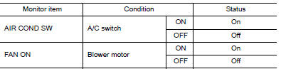
Is the inspection result normal? Yes >> go to 4.
No >> replace a/c switch assembly. Refer to hac-188, "removal and installation".
4.Check ecm input signal
 With consult
Check “air cond sig” and “heater fan sw” in “data monitor” mode of “ecm” using consult.
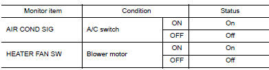
Is the inspection result normal? Yes >> go to 5.
No >> check can communication system. Refer to lan-16, "trouble diagnosis flow chart".
5.Check ipdm E/R input signal
 With consult
- Start engine.
- Check “AC COMP REQ” in “DATA MONITOR” mode of “IPDM E/R” using CONSULT.
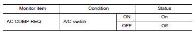
Is the inspection result normal? YES >> Inspection End.
NO >> Check CAN communication system. Refer to LAN-16, "Trouble Diagnosis Flow Chart".
 DTC/circuit diagnosis
POWER SUPPLY AND GROUND CIRCUIT
A/C AUTO AMP.
A/C AUTO AMP. : Diagnosis Procedure
Regarding Wiring Diagram information, refer to HAC-145, "Wiring Diagram" or
HAC-152, "Wiring Diagr ...
 Removal and installation
A/C ASSEMBLY SWITCH
Removal and Installation
Removal
Remove the cvt shift selector finisher (cvt: re0f11a). Refer to tm-253,
"removal and installation".
Remove the MT shift select ...
Other materials:
Steering angle sensor
Exploded View
Steering angle sensor
Screw
Front
Removal and Installation
REMOVAL
Remove spiral cable assembly. Refer to SR-16, "Removal and
Installation".
Remove the two screws and the steering angle sensor from
spiral cable.
INSTALLATION
Ins ...
P0122, P0123 TP Sensor
DTC Logic
DTC DETECTION LOGIC
NOTE:
If DTC P0122 or P0123 is displayed with DTC P0643, first perform the
trouble diagnosis for DTC P0643.
Refer to EC-353, "DTC Logic".
DTC No.
CONSULT screen terms
(Trouble diagnosis content)
DTC detecting condition
Possible caus ...
System
EPS system
EPS SYSTEM : System Description
SYSTEM DIAGRAM
DESCRIPTION
EPS control unit performs an arithmetical operation on data,
such
as steering wheel turning force (sensor signal) from the torque
sensor, vehicle speed signal, etc. Then it generates an optimum
assist torque ...
