Nissan Sentra Service Manual: System
EPS system
EPS SYSTEM : System Description
SYSTEM DIAGRAM
DESCRIPTION
-
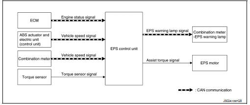
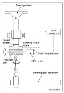
EPS control unit performs an arithmetical operation on data, such as steering wheel turning force (sensor signal) from the torque sensor, vehicle speed signal, etc. Then it generates an optimum assist torque signal to the EPS motor according to the driving condition.
-
In case of a malfunction in the electrical system, the fail-safe function stops output signals to the EPS motor. Refer to STC-9, "EPS SYSTEM : Fail-Safe".
-
EPS control unit decreases the output signal to EPS motor while extremely using the power steering function (e.g., full steering) consecutively for protecting EPS motor and EPS control unit (Overload protection control). Refer to STC-13, "Protection Function".
-
Extensive steering at low speed will cause the EPS control unit and EPS motor to heat up, once temperature reaches critical point EPS control unit will reduce current to reduce heat up. System will recover as temperature lowers (reduced or no assistance).
EPS Warning lamp indication
-
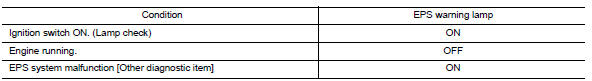
Turn ON when there is a malfunction in EPS system. If indicates that fail-safe mode is engaged and enters a manual steering state (Control turning force steering wheel becomes heavy).
-
Also turns ON when ignition switch is turned ON, for purpose of lamp check. Turns OFF after the engine starts, if system is normal.
CAUTION:
EPS warning lamp also turns ON due to data reception error, CAN communication error etc.
EPS SYSTEM : Fail-Safe
-
If any malfunction occurs in the system and control unit detects the malfunction, EPS warning lamp on combination meter turns ON to indicate system malfunction.
-
When EPS warning lamp is ON, the system enters into a manual steering state. (Control turning force steering wheel becomes heavy.)
-
Under abnormal vehicle speed signal conditions, vehicle speed is judged as constant.
EPS SYSTEM : Protection Function
EPS control unit decreases the output signal to EPS motor while extremely using the power steering function (e.g., full steering) consecutively for protecting EPS motor and EPS control unit (Overload protection control).
While activating overload protection control, the assist torque gradually decreases, and the steering wheel turning force becomes heavy. The normal assist torque is recovered if the steering wheel is not turned for a while.
Warning/indicator/chime list
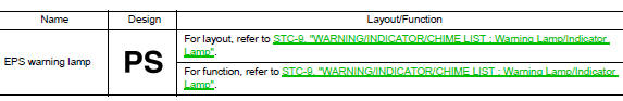
WARNING/INDICATOR/CHIME LIST : Warning Lamp/Indicator Lamp
 Component parts
Component Parts Location
EPS control unit (view with steering
column removed from vehicle)
EPS motor (view with steering column
removed from vehicle)
Torque sensor (view with ...
 Diagnosis system (EPS control unit)
CONSULT Function
FUNCTION
CONSULT can display each diagnostic item using the diagnostic
test modes shown following.
Diagnostic test mode
Function
ECU identification
The part ...
Other materials:
Fuel filler cap warning system
SYSTEM DIAGRAM
SYSTEM DESCRIPTION
The fuel filler cap warning system alerts the driver to the prevention of the
fuel filler being left uncapped and
malfunction occurrences after refueling, by turning ON the fuel filler cap
warning display on the combination
meter.
ECM judges a refuele ...
Door lock and unlock switch
Component function check
1.Check function
Select door lock of bcm using consult.
Select cdl lock sw, cdl unlock sw in data monitor mode.
Check that the function operates normally according to the following
conditions.
Is the inspection result normal?
YES >> Main power windo ...
Basic inspection
Diagnosis and repair work flow
Work Flow
Overall sequence
Detailed flow
1. Get information for symptom
Get the detailed information from the customer about the symptom (the
condition and the environment when
the incident/malfunction occurred).
>> Go to 2.
2. Check dtc
Check ...
