Nissan Sentra Service Manual: Component parts
Component Parts Location
-
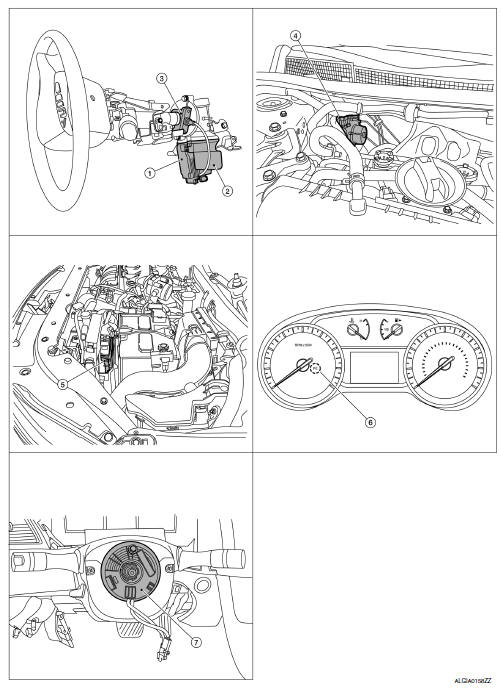
EPS control unit (view with steering column removed from vehicle)
-
EPS motor (view with steering column removed from vehicle)
-
Torque sensor (view with steering column removed from vehicle)
-
ABS actuator and electric unit (control unit)
-
ECM
-
EPS warning lamp (In combination meter)
-
Steering angle sensor (view with steering wheel removed)
Component Description
| Components parts | Reference |
| EPS control unit | STC-6, "EPS Control Unit" |
| EPS motor | STC-6, "EPS Motor, Torque Sensor, Reduction Gear" |
| Torque sensor | STC-6, "EPS Motor, Torque Sensor, Reduction Gear" |
| Reduction gear | STC-6, "EPS Motor, Torque Sensor, Reduction Gear" |
| EPS warning lamp | STC-9, "WARNING/INDICATOR/CHIME LIST : Warning Lamp/ Indicator Lamp" |
| ECM | Transmits mainly the following signals to EPS control unit via
CAN communication.
|
| ABS actuator and electric unit (control unit) | Transmits mainly the following signal to EPS control unit via
CAN communication.
|
| Combination meter | Transmits mainly the following signal to EPS control unit via
CAN communication.
Turns ON the EPS warning lamp according to the signal from EPS control unit via CAN communication. |
EPS Control Unit
-
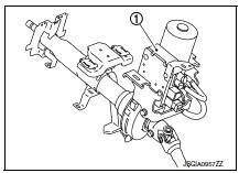
EPS control unit (1) is installed to steering column assembly.
-
EPS control unit performs an arithmetical operation on data, such as steering wheel turning force (sensor signal) from the torque sensor, vehicle speed signal, etc. Then it generates an optimum assist torque signal to the EPS motor according to the driving condition.
-
EPS control unit decreases the output signal to EPS motor while extremely using the power steering function (e.g., full steering) consecutively for protecting EPS motor and EPS control unit (Overload protection control).
EPS Motor, Torque Sensor, Reduction Gear
EPS motor (1), torque sensor (2) and reduction gear (3) are installed to steering column assembly.
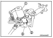
EPS MOTOR
EPS motor provides the assist torque by the control signal from EPS control unit.
TORQUE SENSOR
Torque sensor detects the steering torque, and transmits the signal to EPS control unit.
REDUCTION GEAR
Reduction gear increases the assist torque provided from EPS motor with worm gears, and outputs to the column shaft.

 System
EPS system
EPS SYSTEM : System Description
SYSTEM DIAGRAM
DESCRIPTION
EPS control unit performs an arithmetical operation on data,
such
as steering wheel turning force (sensor signal ...
Other materials:
Body side trim
Exploded View
Rear body side welt
Front body side welt
Tether clip
Front pillar finisher
Metal clip
Dash clip
Dash side finisher
Harness protector
Front kicking plate inner
Center pillar lower finisher
Rear kicking plate inner
Cap
Center pillar upper finisher
Rear p ...
U1001 can comm circuit
Description
CAN (Controller Area Network) is a serial communication line for real time
application. It is an on-vehicle multiplex
communication line with high data communication speed and excellent error
detection ability. Many electronic
control units are equipped onto a vehicle, and each co ...
Wiring diagram
Navigation with bose
Wiring diagram
...
