Nissan Sentra Service Manual: P0122, P0123 TP Sensor
DTC Logic
DTC DETECTION LOGIC
NOTE:
If DTC P0122 or P0123 is displayed with DTC P0643, first perform the trouble diagnosis for DTC P0643.
Refer to EC-353, "DTC Logic".
| DTC No. | CONSULT screen terms (Trouble diagnosis content) | DTC detecting condition | Possible cause |
| P0122 | TP SEN 2/CIRC-B1 (Throttle/Pedal position sensor/switch “A” circuit low) | An excessively low voltage from the TP sensor 2 is sent to ECM. |
|
| P0123 | TP SEN 2/CIRC-B1 (Throttle/Pedal position sensor/switch “A” circuit high) | An excessively high voltage from the TP sensor 2 is sent to ECM. |
DTC CONFIRMATION PROCEDURE
1.PRECONDITIONING
If DTC Confirmation Procedure has been previously conducted, always perform the following procedure before conducting the next test.
- Turn ignition switch OFF and wait at least 10 seconds.
- Turn ignition switch ON.
- Turn ignition switch OFF and wait at least 10 seconds.
TESTING CONDITION:
Before performing the following procedure, confirm that battery voltage is more than 8 V at idle.
>> GO TO 2.
2.PERFORM DTC CONFIRMATION PROCEDURE
- Start engine and let it idle for 1 second.
- Check 1st trip DTC.
1st trip DTC detected? YES >> Proceed to EC-200, "Diagnosis Procedure".
NO >> INSPECTION END
Diagnosis Procedure
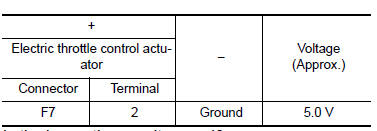
1.CHECK THROTTLE POSITION SENSOR 2 POWER SUPPLY
- Turn ignition switch OFF.
- Disconnect electric throttle control actuator harness connector.
- Turn ignition switch ON.
- Check the voltage between electric throttle control actuator harness connector and ground.
Is the inspection result normal? YES >> GO TO 3.
NO >> GO TO 2.
2.CHECK THROTTLE POSITION SENSOR 2 POWER SUPPLY CIRCUIT
- Turn ignition switch OFF.
- Disconnect ECM harness connector.
- Check the continuity between electric throttle control actuator harness connector and ECM harness connector.
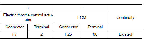
- Also check harness for short to power.
Is the inspection result normal? YES >> Perform the trouble diagnosis for power supply circuit.
NO >> Repair or replace error-detected parts.
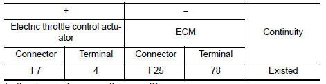
3.CHECK THROTTLE POSITION SENSOR 2 GROUND CIRCUIT
- Turn ignition switch OFF.
- Disconnect ECM harness connector.
- Check the continuity between electric throttle control actuator harness connector and ECM harness connector.
Is the inspection result normal? YES >> GO TO 4.
NO >> Repair or replace error-detected parts.
4.CHECK THROTTLE POSITION SENSOR 2 INPUT SIGNAL CIRCUIT
- Check the continuity between electric throttle control actuator harness connector and ECM harness connector.
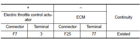
- Also check harness for short to ground and to power.
Is the inspection result normal? YES >> GO TO 5.
NO >> Repair or replace error-detected parts.
5.CHECK THROTTLE POSITION SENSOR
Check throttle position sensor. Refer to EC-202, "Component Inspection (TP Sensor)".
Is the inspection result normal? YES >> Check intermittent incident. Refer to GI-39, "Intermittent Incident".
NO >> Replace electric throttle control actuator. Refer to EM-27, "Removal and Installation".
Component Inspection (TP Sensor)
1.CHECK THROTTLE POSITION SENSOR
- Turn ignition switch OFF.
- Reconnect all harness connectors disconnected.
- Perform “ Throttle Valve Closed Position Learning”. Refer to EC-139, "Work Procedure".
- Turn ignition switch ON.
- Set selector lever to D (CVT) or 1st (M/T) position.
- Check the voltage between ECM harness connector terminals as per the following conditions.
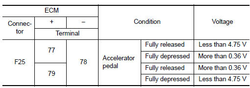
Is the inspection result normal? YES >> INSPECTION END
NO >> Replace electric throttle control actuator. Refer to EM-27, "Removal and Installation".
 P0117, P0118 ECT Sensor
DTC Logic
DTC DETECTION LOGIC
DTC No.
CONSULT screen terms
(Trouble diagnosis content)
DTC detecting condition
Possible cause
P0117
ECT SEN/CIRC
(Engine coolant tem ...
 P0125 ECT Sensor
DTC Logic
DTC DETECTION LOGIC
NOTE:
If DTC P0125 is displayed with P0116, first perform the trouble
diagnosis for DTC P0116. Refer to EC-
196, "DTC Logic".
If DTC P0125 is displ ...
Other materials:
P0131 A/F Sensor 1
DTC Logic
DTC DETECTION LOGIC
To judge the malfunction, the diagnosis checks that the A/F signal computed
by ECM from the A/F sensor 1
signal is not inordinately low.
DTC No.
CONSULT screen terms
(Trouble diagnosis content)
DTC detecting condition
Possible cause
P01 ...
Precaution
Precaution for supplemental restraint system (srs) "air bag" and "seat belt
pre-tensioner"
The Supplemental Restraint System such as “AIR BAG” and “SEAT BELT
PRE-TENSIONER”, used along
with a front seat belt, helps to reduce the risk or severity of injur ...
CONSULT Data Link Connector (DLC) Circuit
Inspection procedure
If the CONSULT cannot diagnose the system properly, check the following
items.
Symptom
Check item
CONSULT cannot access any
system.
CONSULT DLC power supply circuit (Terminal 8 and 16) and ground
circuit (Terminal 4 and 5)
...
