Nissan Sentra B18 (2020-2025) Service Manual: Steering Control System :: Ecu Diagnosis Information. Eps Control Unit
Eps Control Unit. Values on the Diagnosis Tool
Values on the Diagnosis Tool
Note:
The following table includes information (items) inapplicable to this Nissan Sentra vehicle: For information (items) applicable to this vehicle, refer to CONSULT display items.
|
Monitor item |
Data Monitor |
||
|---|---|---|---|
|
Condition |
Display value |
||
|
Steering torque |
Engine running |
Steering wheel: Not steering (There is no steering force) |
Approx. 0.0 Nm |
|
Steering wheel: Right turn |
Positive value (Nm) |
||
|
Steering wheel: Left turn |
Positive value (Nm) |
||
|
Assist level |
Engine running |
100%*1 |
|
|
EPS warning |
Engine running |
EPS system is normal |
No error |
|
Not used |
Error1 |
||
|
EPS system malfunction |
Error2 |
||
|
Demanded assistance torque |
Engine running |
Steering wheel: Not steering (There is no steering force) |
Approx. 0 Nm |
|
Steering wheel: Right turn |
Positive value |
||
|
Steering wheel: Left turn |
Negative value |
||
|
Measured motor current |
Engine running |
Steering wheel: Not steering (There is no steering force) |
Approx. 0 A |
|
Steering wheel: Left or Right turn |
Displays consumption current of EPS motor*2 |
||
|
ECU temperature |
Ignition switch ON or engine running |
Displays temperature of inside of EPS control unit |
|
|
Battery voltage |
Ignition switch ON |
10.5 - 16 V |
|
|
Nissan Sentra Vehicle speed |
Nissan Sentra Vehicle stopped |
0.00 kp/h or mph |
|
|
While driving |
Approximately equal to the indication on speedometer*3 (inside of ┬▒10%) |
||
|
ENGINE STATUS |
Engine not running |
STOP |
|
|
Engine stall |
STALL |
||
|
Engine running |
RUN |
||
|
Engine cranking |
CRANK |
||
*1: Normally displays 100%. In case of an excessive stationary steering, the assist curvature gradually falls. However, it returns to 100% when left standing.
*2: Almost in accordance with the value of ŌĆ£Target motor currentŌĆØ. It is not a malfunction though these values are not accorded when steering quickly
*3: It is not a malfunction, though it might not be corresponding just after ignition switch ON.
Reference Value
Reference Value
TERMINAL LAYOUT
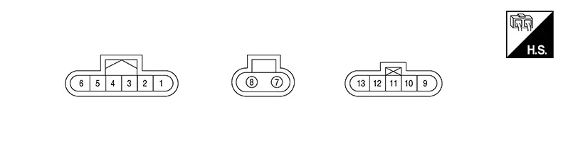
PHYSICAL VALUES
|
Terminal No. (Wire Color) |
Description |
Condition |
Value (Approx.) |
|||
|---|---|---|---|---|---|---|
|
+ |
ŌłÆ |
Signal name |
Input/Output |
|||
|
1 (P) |
ŌĆö |
CAN-Low |
Input/Output |
ŌĆö |
ŌĆö |
|
|
2 (L) |
ŌĆö |
CAN-High |
Input/Output |
ŌĆö |
ŌĆö |
|
|
4 (SB) |
Ground |
Ignition power supply |
Input |
Ignition switch: ON |
Battery voltage |
|
|
Ignition switch: OFF |
0 V |
|||||
|
7 (R) |
Ground |
Battery power supply |
Input |
Always |
Battery voltage |
|
|
8 (B) |
Ground |
Ground |
ŌĆö |
Always |
0 V |
|
|
9 (Y) |
ŌĆö |
ŌĆö |
ŌĆö |
ŌĆö |
ŌĆö |
|
|
10 (W) |
ŌĆö |
ŌĆö |
ŌĆö |
ŌĆö |
ŌĆö |
|
|
12 (BR) |
ŌĆö |
ŌĆö |
ŌĆö |
ŌĆö |
ŌĆö |
|
|
13 (G) |
ŌĆö |
ŌĆö |
ŌĆö |
ŌĆö |
ŌĆö |
|
Fail-Safe
Fail-Safe
-
If any malfunction occurs in the system and control unit detects the malfunction, EPS warning lamp on combination meter turns ON to indicate system malfunction.
-
When EPS warning lamp is ON, the system enters into a manual steering state (control turning force steering wheel becomes heavy).
|
DTC |
Fail-safe condition |
|---|---|
|
C1601-16 |
Manual steering state |
|
C1601-17 |
|
|
C1604-96 |
|
|
C1606-96 |
|
|
C1608-43 |
|
|
C1608-44 |
|
|
C1608-45 |
|
|
C1608-46 |
Normal control |
|
C1608-49 |
Manual steering state |
|
C1608-54 |
Normal control |
|
C161A-82 |
Constant steering assist level |
|
C161A-83 |
|
|
C161A-86 |
|
|
C161B-86 |
|
|
C161B-87 |
|
|
C1624-00 |
Slowly reducing assistance |
|
C161C-82 |
Normal control |
|
C161C-83 |
|
|
C161C-86 |
|
|
C161C-87 |
|
|
C161E-86 |
|
|
C1621-86 |
|
|
C1621-87 |
|
|
C1623-87 |
|
|
C1629-87 |
|
|
C1630-87 |
|
|
U0073-00 |
|
|
U2140-87 |
|
|
U2148-87 |
|
|
U214F-87 |
|
|
U2156-87 |
|
|
U215B-87 |
Protection Function
Protection Function
EPS control unit decreases the output signal to EPS motor while extremely using the power steering function (e.g., full steering) consecutively for protecting EPS motor and EPS control unit (overload protection control). While activating overload protection control, the assist torque gradually decreases, and the steering wheel turning force becomes heavy. The normal assist torque is recovered if the steering wheel is not turned for a while.
Dtc Inspection Priority Chart
DTC Inspection Priority Chart
When multiple DTCs are detected simultaneously, check one by one depending on the following priority list:
|
Priority |
Detected item (DTC) |
|---|---|
|
1 |
|
|
2 |
|
|
3 |
|
Dtc Index
DTC Index
|
DTC |
Display item |
EPS warning lamp |
Refer to |
|---|---|---|---|
|
C1601-16 |
BATTERY VOLT |
ON |
DTC Description |
|
C1601-17 |
BATTERY VOLT |
ON |
DTC Description |
|
C1604-96 |
TORQUE SENSOR |
ON |
DTC Description |
|
C1606-96 |
EPS MOTOR |
ON |
DTC Description |
|
C1608-43 |
CONTROL UNIT |
ON |
DTC Description |
|
C1608-44 |
CONTROL UNIT |
ON |
DTC Description |
|
C1608-45 |
CONTROL UNIT |
ON |
DTC Description |
|
C1608-46 |
CONTROL UNIT |
ON |
DTC Description |
|
C1608-49 |
CONTROL UNIT |
ON |
DTC Description |
|
C1608-54 |
CONTROL UNIT |
ON |
DTC Description |
|
C161A-82 |
ABS system |
OFF |
DTC Description |
|
C161A-83 |
ABS system |
OFF |
DTC Description |
|
C161A-86 |
ABS system |
OFF |
DTC Description |
|
C161B-86 |
ABS system |
OFF |
DTC Description |
|
C161B-87 |
ABS system |
OFF |
DTC Description |
|
C161C-82 |
ST angle sensor system |
OFF |
DTC Description |
|
C161C-83 |
ST angle sensor system |
OFF |
DTC Description |
|
C161C-86 |
ST angle sensor system |
OFF |
DTC Description |
|
C161C-87 |
ST angle sensor system |
OFF |
DTC Description |
|
C161E-86 |
ABS system |
OFF |
DTC Description |
|
C1621-86 |
BCM system |
OFF |
DTC Description |
|
C1621-87 |
BCM system |
OFF |
DTC Description |
|
C1623-87 |
ECM system |
OFF |
DTC Description |
|
C1624-00 |
Signal connector |
OFF |
DTC Description |
|
C1629-87 |
IPDM E/R system |
OFF |
DTC Description |
|
C1630-87 |
CAN COMM CIRCUIT |
OFF |
DTC Description |
|
DTC |
Display item |
EPS warning lamp |
Refer to |
|---|---|---|---|
|
U0073-00 |
Control module comm bus "A" Off |
ON |
DTC Description |
|
U2140-87 |
CAN comm err (ECM) |
OFF |
DTC Description |
|
U2148-87 |
CAN comm err (brake control unit) |
OFF |
DTC Description |
|
U214F-87 |
CAN comm err (BCM) |
OFF |
DTC Description |
|
U2156-87 |
CAN comm err (steering angle sensor) |
OFF |
DTC Description |
|
U215B-87 |
CAN comm err (IPDM E/R) |
OFF |
DTC Description |
If two or more DTCs are detected, refer to DTC Inspection Priority Chart.
Other materials:
Trunk Lid Opener Actuator
Component Function Check
Component Function Check
CHECK FUNCTION
CONSULT
Select "Trunk/back door" in "Active Test" mode of
"BCM(TRUNK)".
Select ŌĆ£OnŌĆØ to check tha ...
Front Bumper
Exploded View
Exploded View
1.
Front bumper side bracket (RH)
2.
Front bumper reinforcement support
(RH)
...
Fail-Safe
Fail-safe
FAIL-SAFE CONTROL BY DTC
BCM performs fail-safe control when any DTC are
detected.
Display contents of CONSULT
Fail-safe
B2C21-23: Seat belt buc ...