Nissan Sentra B18 (2020-2025) Service Manual: Steering Control System :: System Description
Component Parts. Electronic Power Steering System. Electronic Power Steering System
Component Parts Location
Component Parts Location
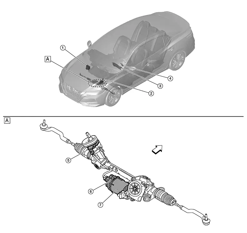
|
|
Steering gear assembly |
|
|
|

 : Nissan Sentra Vehicle front
|
No. |
Component |
Function |
|
|---|---|---|---|
|
1. |
ABS (Ant-lock Braking System) actuator and electric unit (control unit) |
Transmits mainly the following signal to EPS control unit via CAN communication:
Refer to Component Parts Location for detailed component location. |
|
|
2. |
ECM (Engine Control Module) |
Refer to Component Parts Location for detailed component location. |
|
|
3. |
Combination meter [EPS (Electric Power Steering) warning lamp] |
Refer to Component Parts Location (Type A) or Component Parts Location (Type B) for detailed component location. |
|
|
4. |
Chassis control module (with built in steering angle sensor) |
Transmits mainly the following signal to EPS control unit via CAN communication:
Refer to Component Parts Location for detailed component location. |
|
|
5. |
Steering gear assembly |
Torque sensor |
Refer to Steering Gear Assembly. |
|
6. |
EPS (Electric Power Steering) control unit |
||
|
7. |
EPS (Electric Power Steering) motor |
||
Steering Gear Assembly
Steering Gear Assembly
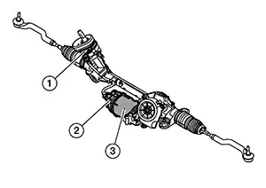
The steering gear assembly is primarily composed of torque sensor (1), EPS control unit (2) and EPS motor (3).
EPS CONTROL UNIT
By receiving steering angle sensor signal ,Nissan Sentra vehicle speed signal and torque sensor signal, the EPS control unit calculates the current of motor drive according to the driving conditions. The EPS control unit controls the EPS motor.
TORQUE SENSOR
Torque sensor detects the steering torque, and transmit the signal to EPS control unit.
EPS MOTOR
The EPS motor provides the assist torque by the signal from EPS control unit.
System. Eps System
System Description
System Description
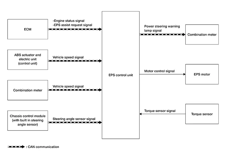
SYSTEM DIAGRAM
INPUT SIGNAL AND OUTPUT SIGNAL
Communicates the signal from each control unit via CAN communication:
|
Control unit |
Signal status |
|---|---|
|
ECM |
Transmits the following signals to EPS control unit via CAN communication:
|
|
ABS actuator and electric unit (control unit) |
Transmits the following signal to EPS control unit via CAN communication:
|
|
Combination meter |
Transmits the following signal to EPS control unit via CAN communication:
Receives the following signal from EPS control unit via CAN communication:
|
|
Chassis control module (with built in steering angle sensor) |
Transmits the following signal to EPS control unit via CAN communication:
|
DESCRIPTION
-
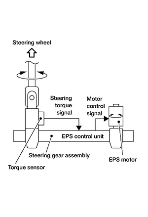
EPS system consists mainly of EPS control unit, EPS motor, torque sensor and steering gear assembly.
-
EPS system calculates a control signal to transmit to the EPS motor based on information received from ECM, ABS actuator and electric unit (control unit), Chassis control module (with built in steering angle sensor) and combination meter via CAN communication.
-
EPS control unit performs an arithmetical operation on data, such as steering wheel turning force (sensor signal) from the torque sensor, Nissan Sentra vehicle speed signal, etc. Then it generates an optimum assist torque signal to the EPS motor according to the driving condition.
-
After engine start, the EPS system performs control.
-
When a malfunction occurs in the system, the fail-safe function stops the EPS system (manual steering state) or restricts its operation (Constant steering assist level state). Refer to Fail Safe.
-
EPS control unit decreases the output signal to EPS motor while extremely using the power steering function (e.g., full steering) consecutively for protecting EPS motor and EPS control unit (Overload protection control). Refer to Protection Function.
EPS WARNING LAMP INDICATION
-
Turns ON when there is a malfunction in EPS system. If ON, fail-safe mode is engaged and the system enters a manual steering state (turning force at steering wheel becomes heavy).
-
Also turns ON when ignition switch is ON, for purpose of lamp check. Turns OFF after the engine starts, if system is normal.
|
Condition |
EPS warning lamp |
|---|---|
|
Ignition switch ON. (Lamp check) |
ON |
|
Engine running |
OFF |
|
EPS system malfunction [Other diagnostic item] |
ON |
CAUTION:
EPS warning lamp also turns ON due to data reception error, CAN communication error etc.
Warning/indicator/chime List
Warning Lamp/indicator Lamp
Warning Lamp/Indicator Lamp
|
Name |
Design |
Layout/Function |
|---|---|---|
|
EPS warning lamp |
|
For layout, refer to Design (Type A). |
|
For layout, refer to Design (Type B). |
||
|
For function, refer to System Description. |

Diagnosis System (eps Control Unit). Consult Function. Consult Function
CONSULT Function
APPLICATION ITEMS
CONSULT can display each diagnostic item using the diagnostic test modes shown following:
|
Diagnosis mode |
CGW Status |
Description |
||
|---|---|---|---|---|
|
Restricted Mode |
Diag Test Mode |
Open Mode |
||
|
Self Diagnostic Result |
Display |
Display |
Display |
Display non-network DTC which EPS control unit memorizes |
|
CGW Information |
Display |
Display |
Display |
|
|
Data Monitor |
Display |
Display |
Display |
Displays EPS control unit input/output data in real time |
|
ECU Identification |
Display |
Display |
Display |
Displays EPS control unit part number |
|
Configuration |
Display |
Display |
Display |
|
|
Network-DTC |
Display |
Display |
Display |
Display network DTC which EPS control unit memorizes when performing "Diagnosis (All System)". |
|
CAN Diag Support Monitor* |
Display |
Display |
Display |
Note: 
The mode is indicated, but not monitored |
*: Displays when performing "Diagnosis (All System)".
CGW INFORMATION
Display the diagnosis mode which a user can perform in Diag Test mode/Open Mode by switching the CGW status from Restricted mode to Diag Test Mode/Open Mode.
For the method of switching CAN Gateway status, refer to CONSULT Function.
SELF DIAGNOSTIC RESULT
Refer to DTC Index.
When “CRNT� is displayed on self-diagnosis result.
-
The system is presently malfunctioning.
When “PAST� is displayed on self-diagnosis result.
-
System malfunction in the past is detected, but the system is presently normal.
Freeze frame data (FFD)
The following Nissan Sentra vehicle status is recorded when DTC is detected and is displayed on CONSULT:
|
Freeze Frame Data Item |
Unit |
Description |
|
|---|---|---|---|
|
Ignition switch counter |
(0 – 255) |
The number of times that ignition switch is ON after the DTC is detected is displayed.
|
|
|
Mileage |
km |
- |
|
DATA MONITOR
Note:
The following table includes information (items) inapplicable to this Nissan Sentra vehicle: For information (items) applicable to this vehicle, refer to CONSULT display items.
|
Monitor item |
Unit |
Remarks |
|---|---|---|
|
Steering torque |
Nm |
Displays steering torque detected by torque sensor. |
|
Assist level |
% |
Displays the current percentage of the allowable assist ratio EPS motor. |
|
EPS warning |
No error / Error1 / Error2 / not used |
EPS warning status is displayed. |
|
Demanded assistance torque |
Nm |
Displays the assist torque of EPS motor being output by the EPS control unit. |
|
Measured motor current |
A |
Displays the current value consumed by EPS motor. |
|
ECU temperature |
°C |
Displays the temperature of the EPS control unit. |
|
Battery voltage |
V |
Displays the power supply voltage. |
|
Nissan Sentra Vehicle speed |
KPH |
Display the Nissan Sentra vehicle speed from vehicle speed signal via CAN communication. |
|
ENGINE STATUS |
Status1 / Status2 / Status3 |
Displays the engine status based on the engine status. |
ECU IDENTIFICATION
Displays the part number stored in the control unit.
CONFIGURATION
Programming includes the following functions:
|
Function |
Description |
|
|---|---|---|
|
Configuration |
Before replacing ECU |
|
|
After replacing ECU |
Allows the writing of Nissan Sentra vehicle information (parts number) stored in CONSULT into the EPS control unit. |
|
Other materials:
Fuel Pump
Component Inspection
Component Inspection
CHECK FUEL PUMP
Turn ignition switch OFF.
Disconnect “fuel level sensor
unit and fuel pump� harness connector.
Check the resistance between
...
Intermittent Incident
Intermittent Incident
Intermittent Incident
DESCRIPTION
Sometimes the symptom is not present when the
vehicle is brought in for service. If possible, re-create the
conditions present at the time of the incident. Doing so may help
avoid a No Trouble Found Diagnosis. The following s ...
U215b Can Comm Err (ipdm E/r)
Dtc Description
DTC Description
DTC DETECTION LOGIC
DTC No.
CONSULT screen terms
(Trouble diagnosis
content)
DTC detection condition
...