Nissan Sentra Service Manual: Shift lock system
Component Function Check
1.CHECK SHIFT LOCK OPERATION (PART 1)
- Turn ignition switch ON.
- Shift the selector lever to park “P” position.
- Attempt to shift the selector lever to any other position with the brake pedal released.
Can the selector lever be shifted to any other position? YES >> Go to TM-241, "Diagnosis Procedure".
NO >> GO TO 2.
2.CHECK SHIFT LOCK OPERATION (PART 2)
Attempt to shift the selector lever to any other position with the brake pedal depressed.
Can the selector lever be shifted to any other position? YES >> Inspection End.
NO >> Go to TM-241, "Diagnosis Procedure".
Diagnosis Procedure
Regarding Wiring Diagram information, refer to TM-136, "Wiring Diagram".
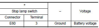
1.CHECK POWER SOURCE (PART 1)
- Turn ignition switch OFF.
- Disconnect stop lamp switch connector.
- Turn ignition switch ON.
- Check the voltage between the stop lamp switch harness connector terminal and ground.
Is the inspection result normal? YES >> GO TO 2.
NO >> GO TO 9.
2.CHECK STOP LAMP SWITCH MOUNTING POSITION
Check stop lamp switch mounting position. Refer to BR-15, "Adjustment".
Is the inspection result normal? YES >> GO TO 3.
NO >> Adjust stop lamp switch mounting position.
3.CHECK STOP LAMP SWITCH
Check stop lamp switch. Refer to TM-243, "Component Inspection (Stop Lamp Switch)".
Is the inspection result normal? YES >> GO TO 4.
NO >> Repair or replace stop lamp switch.
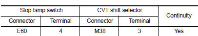
4.CHECK CIRCUIT BETWEEN STOP LAMP SWITCH AND CVT SHIFT SELECTOR (PART 1)
- Disconnect CVT shift selector connector
- Check the continuity between the stop lamp switch harness connector terminal and the CVT shift selector harness connector terminal.
 Is the inspection
result normal?
YES >> GO TO 5.
NO >> Repair or replace damaged parts.
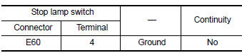
5.CHECK CIRCUIT BETWEEN STOP LAMP SWITCH AND CVT SHIFT SELECTOR (PART 2)
Check the continuity between the stop lamp switch harness connector terminal and ground.
 Is the inspection
result normal?
YES >> GO TO 6.
NO >> Repair or replace damaged parts.
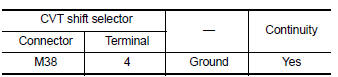
6.CHECK GROUND CIRCUIT
Check the continuity between the CVT shift selector harness connector terminal and ground.
 Is the inspection
result normal?
YES >> GO TO 7.
NO >> Repair or replace damaged parts.
7.CHECK PART POSITION SWITCH
- Disconnect park position switch connector.
- Check park position switch. Refer to TM-243, "Component Inspection (Park Position Switch)".
Is the inspection result normal? YES >> GO TO 8.
NO >> Repair or replace damaged parts.
8.CHECK SHIFT LOCK SOLENOID
- Disconnect shift lock solenoid connector.
- Check shift lock solenoid. Refer to TM-243, "Component Inspection (Shift Lock Solenoid)".
Is the inspection result normal? YES >> GO TO 9.
NO >> Repair or replace damaged parts.
9.DETECT MALFUNCTIONING ITEM
Check the following items:
- Open or short circuit of the harness between ignition switch and stop lamp switch connector. Refer to PG-20, "Wiring Diagram — Ignition Power Supply —"
- Ignition switch
- 10A fuse [No.5, fuse block (J/B)]. Refer to PG-47, "Terminal Arrangement".
Is the inspection result normal? YES >> Check intermittent incident. Refer to GI-39, "Intermittent Incident".
NO >> Repair or replace damaged parts.
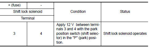
Component Inspection (Shift Lock Solenoid)
1.CHECK SHIFT LOCK SOLENOID
Apply voltage to terminals of shift lock solenoid and park position switch (shift selector) connector and check that shift lock solenoid is activated.
CAUTION:
- Connect a fuse between the terminals when applying voltage.
- Never cause shorting between terminals.
 Is the inspection
result normal?
YES >> Inspection End.
NO >> Replace CVT shift selector. Refer to TM-253, "Removal and Installation".
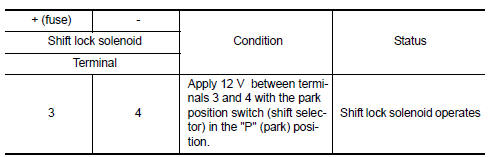
Component Inspection (Park Position Switch)
1.CHECK PARK POSITION SWITCH (SHIFT SELECTOR)
Apply voltage to terminals of shift lock solenoid and park position switch (shift selector) connector and check that shift lock solenoid is activated.
CAUTION:
- Connect a fuse between the terminals when applying voltage.
- Never cause shorting between terminals.
 Is the inspection
result normal?
YES >> Inspection End.
NO >> Replace CVT shift selector. Refer to TM-253, "Removal and Installation".
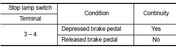
Component Inspection (Stop Lamp Switch)
1.CHECK STOP LAMP SWITCH
Check the continuity between the stop lamp switch connector terminals.
 Is the inspection
result normal?
YES >> Inspection End.
NO >> Replace stop lamp switch. Refer to BR-22, "Exploded View".
 Shift position indicator circuit
Component Parts Function Inspection
1.CHECK SHIFT POSITION INDICATOR
Start the engine.
Shift selector lever.
Check that the selector lever position and the shift position indicator
on the ...
 Symptom diagnosis
CVT CONTROL SYSTEM
Symptom Table
The diagnosis item number indicates the order of check. Start checking in the
order from 1.
...
Other materials:
Precaution for work
When removing or disassembling each component, be careful not to damage
or deform it. If a component
may be subject to interference, be sure to protect it with a shop cloth.
When removing (disengaging) components with a screwdriver or similar
tool, be sure to wrap the component
with a ...
Diagnosis system (bcm) (with intelligent
key system)
Common item
Common item : consult function (bcm -
common item)
APPLICATION ITEM
CONSULT performs the following functions via CAN communication with BCM.
Direct Diagnostic Mode
Description
ECU identification
The BCM part number is displayed.
Self Diagnostic Result
...
Service Notice or Precautions for Steering System
In case of removing steering gear assembly, make the final
tightening with grounded and unloaded vehicle
condition, and then check wheel alignment.
Observe the following precautions when disassembling.
Before disassembly, thoroughly clean the outside of the
unit.
...
