Nissan Sentra Service Manual: Charging system preliminary inspection
Diagnosis Procedure
1.CHECK BATTERY TERMINALS CONNECTION
Check if battery terminals are clean and tight.
Is the inspection result normal? YES >> GO TO 2.
NO >> Repair battery terminal connection. Confirm repair by performing complete Charging system test using EXP-800 NI or GR8-1200 NI (if available). Refer to the applicable Instruction Manual for proper testing procedures.
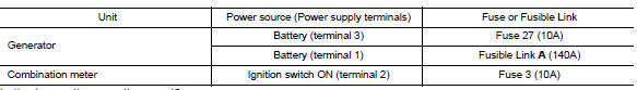
2.Check fuse
Check for blown fuse and fusible link.
Is the inspection result normal? Yes >> go to 3.
No >> replace the blown fuse or fusible link after repairing the affected circuit.
3.Check generator ground terminal connection
Check if connector f17 terminal 5 and 6 is clean.
Is the inspection result normal? Yes >> go to 4.
No >> repair connection.
4.Check drive belt tension
Check drive belt tension. Refer to chg-29, "removal and installation".
Is the inspection result normal? Yes >> inspection end.
No >> repair as needed.

 Power generation voltage variable control system operation inspection
Diagnosis Procedure
Regarding wiring diagram information. Refer to chg-9, "wiring diagram".
Caution:
When performing this inspection, always use a charged battery that has
completed the ...
Other materials:
Vehicle Recovery (Freeing a Stuck Vehicle)
Front
Remove the hook cover from the bumper using a remover tool.
Securely install the vehicle recovery hook stored with jacking
tools.
Check that the hook is properly secured in the stored place after use.
WARNING:
Stand clear of a stuck vehicle.
Do not spin your tires at high s ...
The ambient temperature display is incorrect
Description
The displayed outside air temperature is higher than the actual
temperature.
The displayed outside air temperature is lower than the actual
temperature.
Outside air temperature is not indicated.
Diagnosis procedure
1.Check ambient sensor signal circuit
Check the ambie ...
Diagnosis system (bcm) (without intelligent key system)
Common item
COMMON ITEM : CONSULT Function (BCM - COMMON ITEM)
APPLICATION ITEM
CONSULT performs the following functions via CAN communication with BCM.
SYSTEM APPLICATION
BCM can perform the following functions.
Wiper
Wiper : consult function (bcm - wiper)
DATA MONITOR
ACTIVE TES ...
