Nissan Sentra Service Manual: Steering switch (meter control switch) signal circuit
Diagnosis Procedure
Regarding wiring diagram information, refer to mwi-28, "wiring diagram".
1.Check combination meter input signal
- Turn ignition switch on.
- Measure voltage between the following terminals of the combination meter.
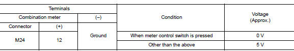
Is the inspection result normal? Yes >> inspection end.
No >> go to 2.
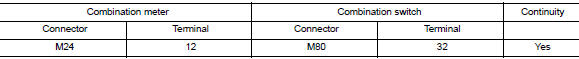
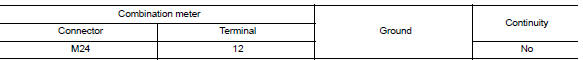
2.Check steering switch signal circuit
- Turn ignition switch OFF.
- Disconnect combination meter connector m24 and combination switch connector m80.
- Check continuity between combination meter harness connector and steering switch harness connector.
- Check continuity between combination meter harness connector and ground.
Is the inspection result normal? Yes >> inspection end.
No >> repair or replace harness or connector.
Component Inspection
1.Check steering switch
Check continuity between spiral cable terminals.
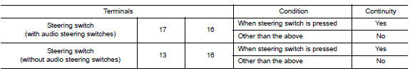
Is the inspection result normal? Yes >> inspection end.
No >> replace steering switch. Refer to st-10, "removal and installation".
 Power supply and ground circuit
Combination meter
COMBINATION METER : Diagnosis Procedure
Regarding Wiring Diagram information, refer to MWI-28, "Wiring Diagram".
1.Check fuses
Check that the following fuses are not bl ...
 Illumination control switch signal circuit
Diagnosis procedure
Regarding wiring diagram information, refer to mwi-28, "wiring diagram".
1.Check combination meter input signal
Turn ignition switch on.
Check voltage between the ...
Other materials:
Aluminum alloy wheels
Wash the wheels regularly with a sponge dampened
in a mild soap solution, especially during
winter months in areas where road salt is used. If
not removed, road salt can discolor the wheels.
CAUTION
Follow the directions below to avoid
staining or discoloring the wheels:
Do not use a clean ...
Precaution
Precaution for supplemental restraint system (srs) "air bag" and "seat belt
pre-tensioner"
The Supplemental Restraint System such as “AIR BAG” and “SEAT BELT
PRE-TENSIONER”, used along
with a front seat belt, helps to reduce the risk or severity of injur ...
U1010 Control unit (CAN)
Description
Initial diagnosis of ABS actuator and electric unit (control
unit)
DTC Logic
DTC DETECTION LOGIC
DTC
Items
(CONSULT screen terms)
DTC detection condition
Possible cause
U1010
CONTROL UNIT (CAN)
When detecting error during the initial diagnosis
...
