Nissan Sentra Service Manual: Power supply and ground circuit
Combination meter
COMBINATION METER : Diagnosis Procedure
Regarding Wiring Diagram information, refer to MWI-28, "Wiring Diagram".
1.Check fuses
Check that the following fuses are not blown.
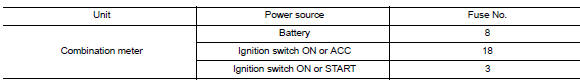
Is the fuse blown? Yes >> replace the blown fuse after repairing the affected circuit.
No >> go to 2.
2.Power supply circuit check
Check voltage between combination meter harness connector m24 terminals 15, 27, 28 and ground
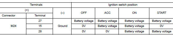
Is the inspection result normal? YES >> GO TO 3.
NO >> Repair or replace harness or connector.
3.Check ground circuit
Check continuity between combination meter harness connector m24 terminals 21, 22, 23 and ground.
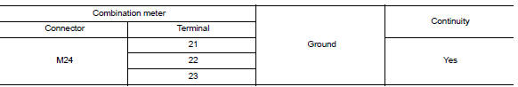
Is the inspection result normal? Yes >> inspection end.
No >> repair or replace harness or connector.
Bcm (body control system) (with intelligent key system)
Bcm (body control system) (with intelligent key system) : diagnosis procedure
Regarding wiring diagram information, refer to bcs-51, "wiring diagram".
1.Check fuses and fusible link
Check that the following fuses and fusible link are not blown.
Is the fuse blown? Yes >> replace the blown fuse or fusible link after repairing the affected circuit.
No >> go to 2.
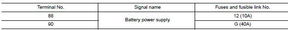
2.Check power supply circuit
- Disconnect bcm connector m85.
- Check voltage between BCM connector M85 and ground.
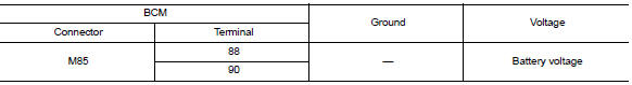
Is the inspection result normal? Yes >> go to 3.
No >> repair harness or connector.
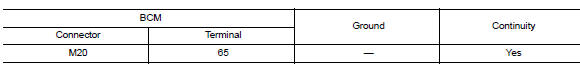
3.Check ground circuit
Check continuity between bcm connector m85 and ground.
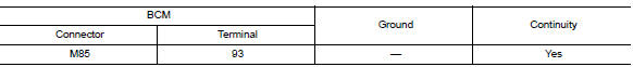
Is the inspection result normal? Yes >> inspection end.
No >> repair harness or connector.
Bcm (body control system) (without intelligent key system)
Bcm (body control system) (without intelligent key system) : diagnosis procedure
Regarding Wiring Diagram information, refer to BCS-111, "Wiring Diagram".
1.Check fuses and fusible link
Check that the following fuses and fusible link are not blown.
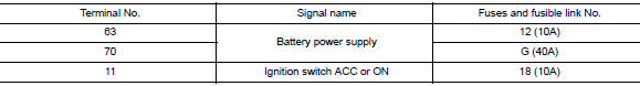
Is the fuse blown? Yes >> replace the blown fuse or fusible link after repairing the affected circuit.
No >> go to 2.
2.Check power supply circuit
- Turn ignition switch off.
- Disconnect bcm connectors.
- Check voltage between bcm connector and ground.
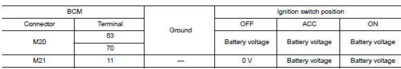
Is the inspection result normal? YES >> GO TO 3.
NO >> Repair harness or connector.
3.Check ground circuit
Check continuity between BCM connector and ground.
Is the inspection result normal? Yes >> inspection end.
No >> repair harness or connector.
 B2268 water temp
Description
The engine coolant temperature signal is transmitted from ecm to the
combination meter via can communication.
Dtc logic
Dtc detection logic
Dtc
Consult
Detection condit ...
 Steering switch (meter control switch) signal circuit
Diagnosis Procedure
Regarding wiring diagram information, refer to mwi-28, "wiring diagram".
1.Check combination meter input signal
Turn ignition switch on.
Measure voltage between ...
Other materials:
Bcm branch line circuit
Diagnosis Procedure
1.Check connector
Turn the ignition switch off.
Disconnect the battery cable from the negative terminal.
Check the terminals and connectors of the BCM for damage, bend and loose
connection (unit side and
connector side).
Is the inspection result normal?
YES > ...
B1429 Seat belt buckle switch RH
Description
DTC B1429 SEAT BELT BUCKLE SWITCH RH
The air bag diagnosis sensor unit monitors the seat belt buckle switch RH
status. If the control unit detects an
open or short condition in the circuit, it will set the DTC.
PART LOCATION
Refer to SRC-5, "Component Parts Location".
D ...
Precaution for Work
When removing or disassembling each component, be careful not to damage
or deform it. If a component
may be subject to interference, be sure to protect it with a shop cloth.
When removing (disengaging) components with a screwdriver or similar
tool, be sure to wrap the component
with a ...
