Nissan Sentra Service Manual: Ecu diagnosis information
Bcm
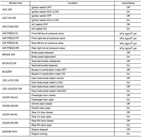
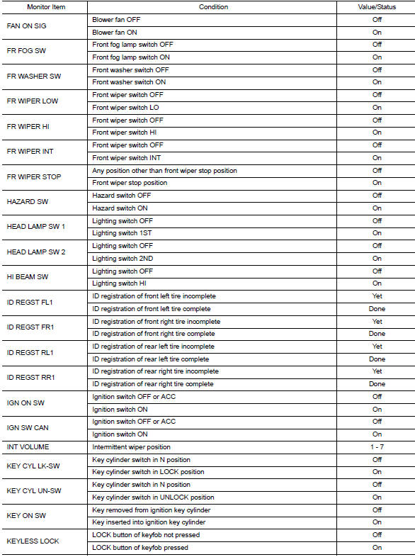
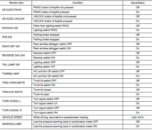
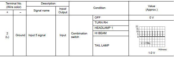
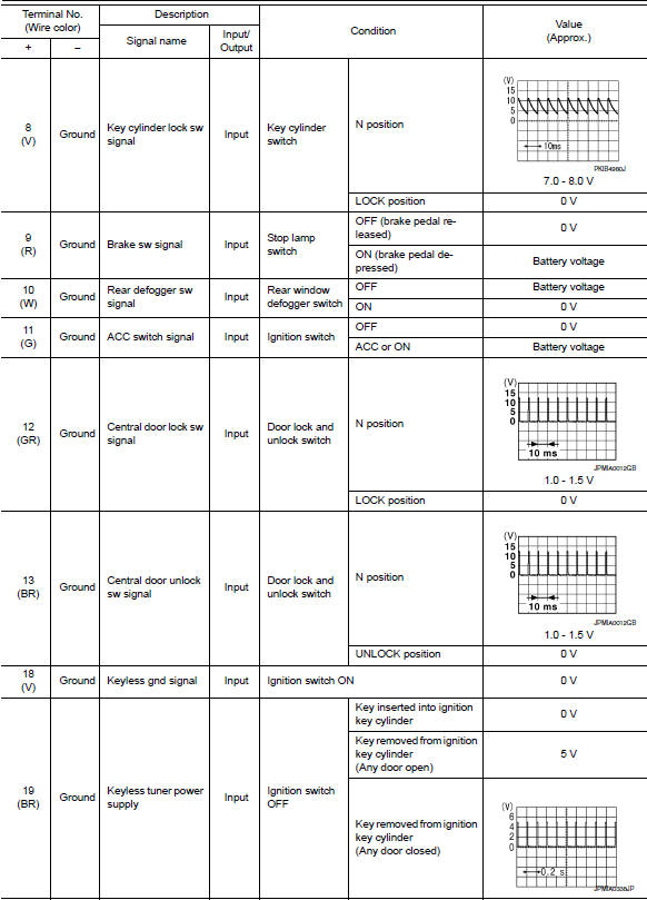
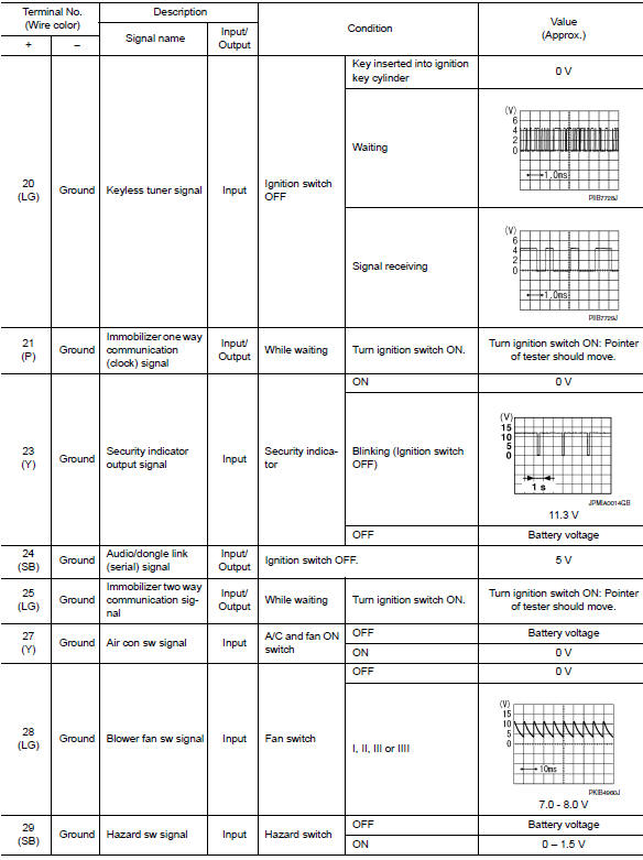
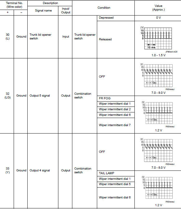
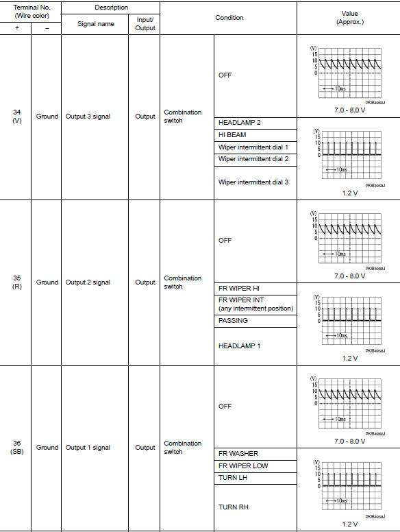
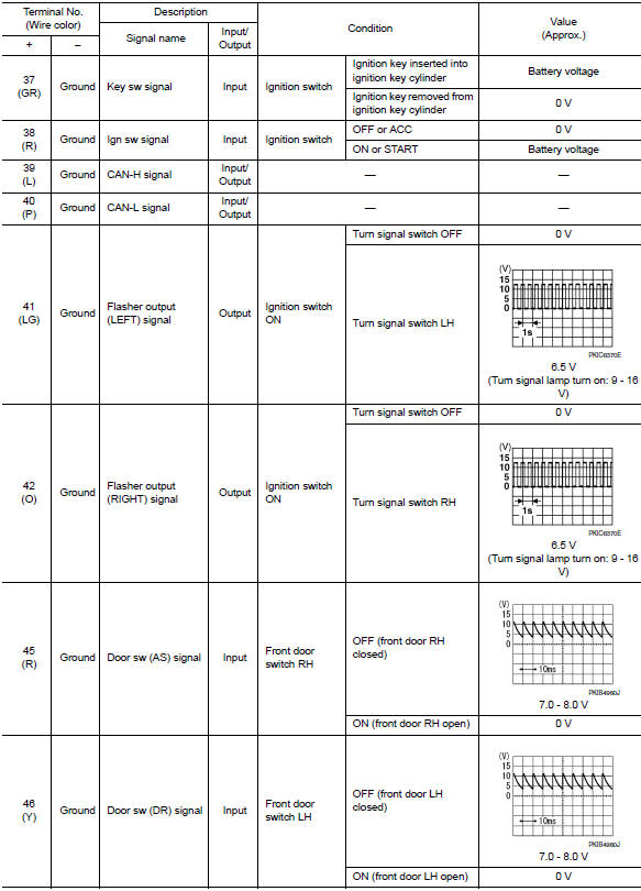
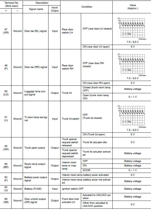
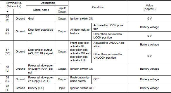
Reference value
NOTE:
The Signal Tech II Tool (J-50190) can be used to perform the following functions. Refer to the Signal Tech II User Guide for additional information.
- Activate and display TPMS transmitter IDs
- Display tire pressure reported by the TPMS transmitter
- Read TPMS DTCs
- Register TPMS transmitter IDs
- Test remote keyless entry keyfob relative signal strength
VALUES ON THE DIAGNOSIS TOOL
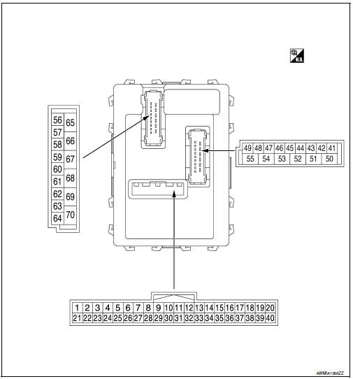
Terminal layout
Physical values

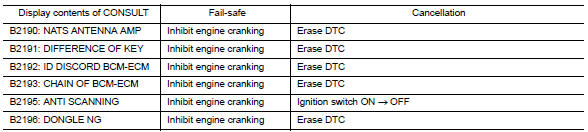
Fail-safe
Fail-safe control by dtc
Bcm performs fail-safe control when any dtc are detected.
Fail-safe control of combination switch reading function caused by low power supply voltage
If voltage of battery power supply lower, BCM maintains combination switch reading to the status when input voltage is less than approximately 9 V.
Note:
When voltage of battery power supply is approximately 9 v or more, combination switch reading function returns to normal operation.
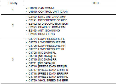
Dtc inspection priority chart
If some dtcs are displayed at the same time, perform inspections one by one based on the following priority chart.
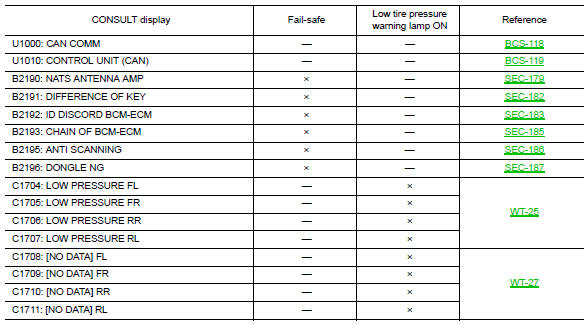
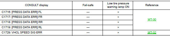
Dtc index
Note:
Details of time display
- Crnt: displays when there is a malfunction now or after returning to the normal condition until turning ignition switch off ƒ¸ on again.
- 1 - 39: Displayed if any previous malfunction is present when current condition is normal. It increases like 1 → 2 → 3...38 → 39 after returning to the normal condition whenever ignition switch OFF → ON. The counter remains at 39 even if the number of cycles exceeds it. It is counted from 1 again when turning ignition switch OFF → ON after returning to the normal condition if the malfunction is detected again.
 Diagnosis system (bcm)
Common item
Common item : consult function (bcm - common item)
APPLICATION ITEM
CONSULT performs the following functions via CAN communication with BCM.
Direct Diagnostic Mode
Descriptio ...
 Wiring diagram
BCM
Wiring diagram
...
Other materials:
Steering knuckle
Exploded View
Steering knuckle
Splash guard
Wheel stud
Wheel hub and bearing
Disc brake rotor
Wheel hub lock nut
Nut retainer
Cotter pin
Removal and Installation
REMOVAL
Remove the wheel and tire using power tool. Refer to WT-47, "Exploded
View".
Remove ...
P1651 Starter motor relay
Description
ECM controls ON/OFF state of the starter relay, according to the engine and
vehicle condition. ECM transmits
a control signal to IPDM E/R by CAN communication.
Under normal conditions, ECM controls and maintains the starter relay in OFF
state during following condition:
Engi ...
U1000 can comm circuit
Dtc logic
Dtc detection logic
Dtc
Consult
Detection condition
Possible malfunction location
U1000
Can comm circ
[u1000]
When combination meter is not receiving can communication
signals for 2 seconds or more.
Combination meter
Diagnosis procedure
1.Ch ...
