Nissan Sentra Service Manual: Steering knuckle
Exploded View
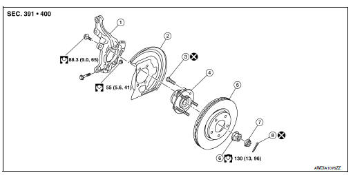
- Steering knuckle
- Splash guard
- Wheel stud
- Wheel hub and bearing
- Disc brake rotor
- Wheel hub lock nut
- Nut retainer
- Cotter pin
Removal and Installation
REMOVAL
- Remove the wheel and tire using power tool. Refer to WT-47, "Exploded View".
- Remove the nut and disconnect the steering outer socket from the steering knuckle. Refer to ST-14, "Removal and Installation".
- Remove the nut and bolt from the lower ball joint. Disconnect the steering knuckle from the transverse link.
- Remove the wheel hub and bearing from the steering knuckle. Refer to FAX-8, "Removal and Installation".
- Remove the splash guard from the steering knuckle.
- Suspend the drive shaft with suitable wire.
- Remove the lower strut nuts and bolts (

). Refer to FSU-8, "Exploded View".
- Remove the steering knuckle.
- Inspect the components. Refer to FSU-15, "Inspection".
INSTALLATION
Installation is in the reverse order of the removal.
CAUTION:
Do not reuse cotter pin.
- Complete the inspection. Refer to FSU-15, "Inspection".
Inspection
INSPECTION AFTER REMOVAL
Check the following items, and replace the part if necessary.
- Check components for deformation, cracks, and other damage.
- Check boots of transverse link and steering outer socket ball joint for breakage, axial end play, and swing torque.
- Transverse link: Refer to FSU-10, "Inspection".
- Steering outer socket: Refer to ST-8, "Inspection".
INSPECTION AFTER INSTALLATION
- Check the wheel sensor harness to be sure the connectors are fully seated.
- Check the wheel alignment. Refer to FSU-6, "Inspection".
 Front stabilizer
Exploded View
Stabilizer bar
Stabilizer clamp
Stabilizer bushing
Stabilizer connecting rod
Front coil spring and strut
Front suspension member
Front
Removal and Installation
RE ...
 Unit removal and installation
Front suspension member
Exploded View
Upper link
Front suspension member
Member stay
Front
Upper link
Front suspension member
Member stay
Front
Removal and Installat ...
Other materials:
Headlining
Exploded View
STANDARD ROOF
Headlining
Assist grip
Map lamp bracket
Sun visor (RH)
Sun visor cover
Sun visor holder
Map lamp
Sun visor (LH)
Interior room lamp
Assist grip cap
Headlining clip
Metal clip
Pawl
Metal clip
Sunroof
Headlining
Assist grip
...
Eps branch line circuit
Diagnosis Procedure
1.Check connector
Turn the ignition switch off.
Disconnect the battery cable from the negative terminal.
Check the terminals and connectors of the eps control unit for damage,
bend and loose connection (unit
side and connector side).
Is the inspection result norm ...
Symptom diagnosis
Audio system
Symptom table
Related to audio
Related to hands-free phone
Before performing diagnosis, confirm that the cellular phone being used
by the customer is compatible with
the vehicle.
It is possible that a malfunction is occurring due to a version change
of the p ...
