Nissan Sentra Service Manual: Front stabilizer
Exploded View
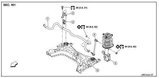
- Stabilizer bar
- Stabilizer clamp
- Stabilizer bushing
- Stabilizer connecting rod
- Front coil spring and strut
- Front suspension member
 Front
Front
Removal and Installation
REMOVAL
- Remove the wheel and tire using power tool. Refer to WT-47, "Exploded View".
- Remove the nut and disconnect the stabilizer connecting rod from the stabilizer bar.
- Remove the front suspension member. Refer to FSU-16, "Removal and Installation".
- Remove the stabilizer clamp bolts (
 ).
). - Remove the stabilizer clamps.
- Remove the stabilizer bushings.
- Remove the stabilizer bar.
- Inspect the components. Refer to FSU-13, "Inspection".
INSTALLATION
Installation is in the reverse order of removal.
- Install the stabilizer bushing with the slit (B) facing toward the front
of the vehicle (
 ).
). - Install the stabilizer clamp with oblong hole (A) facing toward the
front of the vehicle (
 ).
).
- Install the stabilizer clamp bolts in the order of 1 to 5 as shown.
Manual tightening : 1
Temporary tightening : 2 → 3
Final tightening (Specified torque) : 4 → 5
 : Front
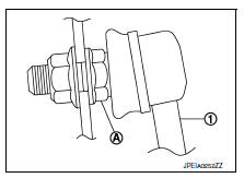
- To connect the stabilizer connecting rod (1), tighten the nut while holding the hexagonal part (A) on the stabilizer connecting rod.
CAUTION:
Do not reuse stabilizer connecting rod nuts.
- Perform the final tightening of the nuts and bolts under unladen conditions with the tires on level ground.
- Complete the inspection. Refer to FSU-13, "Inspection".
Inspection
INSPECTION AFTER REMOVAL
Check the stabilizer bar, the stabilizer connecting rods, the stabilizer bushings, and the stabilizer clamps for deformation, cracks or damage. Replace components if necessary.
INSPECTION AFTER INSTALLATION
- Check the neutral position of the steering angle sensor. Refer to BRC-54, "Work Procedure".
- Check the wheel alignment. Refer to FSU-6, "Inspection".
 Transverse link
Exploded View
Upper link
Front suspension member
Transverse link
Front
Removal and Installation
REMOVAL
Remove the wheel and tire using power tool. Refer to WT-47, "Explode ...
 Steering knuckle
Exploded View
Steering knuckle
Splash guard
Wheel stud
Wheel hub and bearing
Disc brake rotor
Wheel hub lock nut
Nut retainer
Cotter pin
Removal and Installation
REMOVAL
...
Other materials:
Low tire pressure warning lamp blinks
Diagnosis Procedure
NOTE:
If low tire pressure warning lamp repeats blinking ON for 2 seconds and
OFF for 0.2 seconds, wake-up operation
for all transmitters is not complete.
Carry out transmitter wake-up operation. Refer to WT-22, "Work Procedure".
1.CHECK BCM CONNECTOR
Turn ...
Preparation
Special Service Tools
The actual shape of the tools may differ from those illustrated here.
Commercial Service Tools
Clip list
Descriptions for Clips
Replace any clips which are damaged during removal or installation.
...
Auto operation does not operate but manual operate normally (driver side)
Diagnosis Procedure
1.PERFORM INITIALIZATION PROCEDURE
Initialization procedure is executed and operation is confirmed.
Refer to PWC-29, "Work Procedure".
Is the inspection result normal?
YES >> INSPECTION END
NO >> GO TO 2.
2.CHECK ENCODER CIRCUIT
Check encoder cir ...
