Nissan Sentra Service Manual: Illumination control switch signal circuit
Diagnosis procedure
Regarding wiring diagram information, refer to mwi-28, "wiring diagram".
1.Check combination meter input signal
- Turn ignition switch on.
- Check voltage between the following terminals of the illumination control switch.
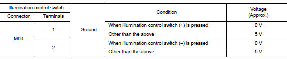
Is the inspection result normal? YES >> Inspection End.
NO >> GO TO 2.
2.Check illumination control switch signal circuit
- Turn ignition switch off
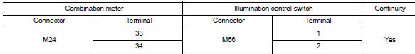
- Disconnect combination meter connector m24 and illumination control switch connector m66.
- Check continuity between combination meter harness connector and illumination control switch harness connector.
- Check continuity between combination meter harness connector and ground.
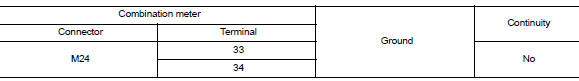
Is the inspection result normal? Yes >> check illumination control switch. Refer to mwi-56, "component inspection".
No >> repair or replace harness or connector.
Component inspection
1.Check illumination control switch
- Turn ignition switch OFF.
- Disconnect illumination control switch connector.
- Check illumination control switch.
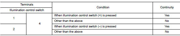
Is the inspection result normal? Yes >> inspection end.
No >> replace illumination control switch. Refer to mwi-80, "removal and installation".
 Steering switch (meter control switch) signal circuit
Diagnosis Procedure
Regarding wiring diagram information, refer to mwi-28, "wiring diagram".
1.Check combination meter input signal
Turn ignition switch on.
Measure voltage between ...
 Fuel level sensor signal circuit
Description
The fuel level sensor unit and fuel pump detects the approximate fuel level
in the fuel tank and transmits the
fuel level signal to the combination meter.
Component function check
1 ...
Other materials:
Liquid Gasket
REMOVAL OF LIQUID GASKET SEALING
After removing the bolts and nuts, separate the mating surface and
remove the liquid gasket using Tool (A).
Tool Number : KV10111100 (J-37228)
CAUTION:
Be careful not to damage the mating surfaces.
In areas where the cutter is difficult to use, use ...
Interior room lamp control circuit
Description
Controls each interior room lamp (ground side) by pwm signal.
Note:
Pwm signal control period is approximately 250 hz (in the gradual
brightening/dimming).
Component function check
Caution:
Before performing the diagnosis, check that the following are normal.
Interior room l ...
The key warning does not sound
(without intelligent key)
Description
The key warning chime does not sound, when all of the following conditions
are fulfilled.
Key inserted into the key cylinder (key switch signal on).
Ignition switch is in acc or off (ignition switch signal off).
Driver side door is open (driver side door switch on)
Diagnosi ...
