Nissan Sentra Service Manual: Liquid Gasket
REMOVAL OF LIQUID GASKET SEALING
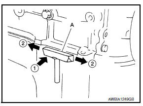
- After removing the bolts and nuts, separate the mating surface and remove the liquid gasket using Tool (A).
Tool Number : KV10111100 (J-37228)
CAUTION:
Be careful not to damage the mating surfaces.
- In areas where the cutter is difficult to use, use a plastic hammer to lightly tap (1) the cutter where the liquid gasket is applied. Use a plastic hammer to slide (2) the cutter by tapping on the side.
CAUTION:
Do not damage the mating surfaces.
LIQUID GASKET APPLICATION PROCEDURE
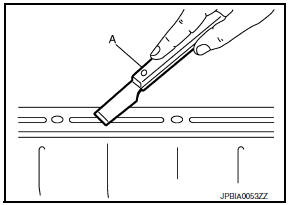
- Using suitable tool (A), remove old liquid gasket adhering to the liquid gasket application surface and the mating surface.
- Remove liquid gasket completely from the groove of the liquid gasket application surface, mounting bolts, and bolt holes.
- Wipe the liquid gasket application surface and the mating surface with white gasoline (lighting and heating use) to remove adhering moisture, grease and foreign materials.
- Attach liquid gasket tube to the suitable tool.
Use Genuine Silicone RTV Sealant, or equivalent. Refer to GI-21, "Recommended Chemical Products and Sealants".
- Apply liquid gasket without gaps to the specified location according to the specified dimensions.
- If there is a groove for liquid gasket application, apply liquid gasket to the groove.

- As for bolt holes (B), normally apply liquid gasket inside the
holes. Occasionally, it should be applied outside the holes.
Check to read the text of this manual.
(A) : Groov
 Inside
- Within five minutes of liquid gasket application, install the mating component.
- If liquid gasket protrudes, wipe it off immediately.
- Do not retighten mounting bolts or nuts after the installation.
- After 30 minutes or more have passed from the installation, fill engine oil and engine coolant.
CAUTION:
If there are specific instructions in the procedures contained in this manual concerning liquid gasket application, observe them.
 Parts Requiring Angle Tightening
Use the Tool for the final tightening of the following engine parts:
Tool number : KV10112100 (BT-8653-A)
Camshaft sprocket (INT) bolt
Cylinder head bolts
Main bearing cap bolts
Connec ...
 Preparation
...
Other materials:
Diagnosis system (bcm) (with intelligent key system)
Common item
Common item : consult function (bcm - common item)
APPLICATION ITEM
CONSULT performs the following functions via CAN communication with BCM.
SYSTEM APPLICATION
BCM can perform the following functions.
Wiper
Wiper : consult function (bcm - wiper)
DATA MONITOR
ACTIVE TES ...
Diagnosis system (bcm) (without intelligent key system)
Common item
COMMON ITEM : CONSULT Function (BCM - COMMON ITEM)
APPLICATION ITEM
CONSULT performs the following functions via CAN communication with BCM.
Direct Diagnostic Mode
Description
ECU identification
The BCM part number is displayed.
Self Diagnostic Result
...
Abs branch line circuit
Diagnosis procedure
1.Check connector
Turn the ignition switch off.
Disconnect the battery cable from the negative terminal.
Check the terminals and connectors of the abs actuator and electric unit
(control unit) for damage, bend
and loose connection (unit side and connector side).
...
