Nissan Sentra Service Manual: Service equipment
RECOVERY/RECYCLING RECHARGING EQUIPMENT
Be certain to follow the manufacturer’s instructions for machine operation and machine maintenance. Do not introduce any refrigerant other than that specified into the machine.
ELECTRICAL LEAK DETECTOR
Be certain to follow the manufacturer’s instructions for tester operation and tester maintenance
VACUUM PUMP
The oil contained inside the vacuum pump is not compatible with the specified oil for HFC-134a (R-134a) A/C systems. The vent side of the vacuum pump is exposed to atmospheric pressure, so the vacuum pump oil may migrate out of the pump into the service hose.
This is possible when the pump is switched OFF after evacuation (vacuuming) and hose is connected to it.
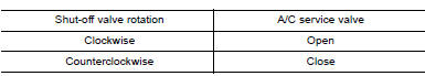
To prevent this migration, use a manual valve placed near the hoseto- pump connection, as per the following.
- Vacuum pumps usually have a manual isolator valve as part of the pump. Close this valve to isolate the service hose from the pump.
- Use a hose equipped with a manual shut-off valve near the pump end for pumps without an isolator. Close the valve to isolate the hose from the pump.
- Disconnect the hose from the pump if the hose has an automatic shut-off valve. As long as the hose is connected, the valve is open and lubricating oil may migrate.
Some one-way valves open when vacuum is applied and close under no vacuum condition. Such valves may restrict the pump’s ability to pull a deep vacuum and are not recommended.
MANIFOLD GAUGE SET
Be certain that the gauge face indicates HFC-134a or R-134a. Be sure the gauge set has 1/2″-16 ACME threaded connections for service hoses. Confirm the set has been used only with refrigerant HFC-134a (R-134a) and specified oils.
SERVICE HOSES
Be certain that the service hoses display the markings described (colored hose with black stripe). All hoses must equip positive shutoff devices (either manual or automatic) near the end of the hoses opposite to the manifold gauge.
SERVICE COUPLERS
Do not attempt to connect HFC-134a (R-134a) service couplers to the CFC-12 (R-12) A/C system. The HFC-134a (R-134a) couplers do not properly connect to the CFC-12 (R-12) system. However, if an improper connection is attempted, discharging and contamination may occur.
REFRIGERANT WEIGHT SCALE
Verify that no refrigerant other than HFC-134a (R-134a) and specified oils have been used with the scale. The hose fitting must be 1/ 2″-16 ACME if the scale controls refrigerant flow electronically.
CHARGING CYLINDER
Using a charging cylinder is not recommended. Refrigerant may be vented into air from cylinder’s top valve when filling the cylinder with refrigerant. Also, the accuracy of the cylinder is generally less than that of an electronic scale or of quality recycle/recharge equipment.
 Precautions for refrigerant system service
WORKING WITH HFC-134a (R-134a)
CAUTION:
CFC-12 (R-12) refrigerant and HFC-134a (R-134a) refrigerant are
not compatible. Compressor malfunction
is likely to occur if the refrigerants are mixe ...
 Preparation
Special service tool
The actual shape of the tools may differ from those illustrated here.
HFC-134a (r-134a) service tool and equipmen.T.
Do not mix HFC-134a (R-134a) refrigerant and/or its s ...
Other materials:
Diagnosis system (AIR BAG)
Description
CAUTION:
Never use electrical test equipment on any circuit related to the
SRS unless instructed in this Service
Manual. SRS wiring harnesses can be identified by yellow and/or orange
harnesses or harness
connectors.
Never repair, splice or modify the SRS wiring harness. ...
Service Notice and Precautions for Road Wheel
Genuine NISSAN aluminum wheel is designed for each type of vehicle. Use
it on the specified vehicle only.
Use Genuine NISSAN parts for the road wheels, valve caps and wheel nuts.
Always use them after adjusting the wheel balance. For the balance
weights, use Genuine NISSAN aluminum
wh ...
Satellite radio reception (if so equipped)
When the satellite radio is used for the first time
or the battery has been replaced, the satellite
radio may not work properly. This is not a malfunction.
Wait more than 10 minutes with satellite
radio ON and the vehicle outside of any metal or
large building for satellite radio to receive a ...
