Nissan Sentra Service Manual: Basic inspection
DIAGNOSIS AND REPAIR WORK FLOW
Work Flow
NOTE:
“DTC” includes DTC at the 1st trip.
1.OBTAIN INFORMATION ABOUT SYMPTOM
Refer to TM-140, "Diagnostic Work Sheet" and interview the customer to obtain the malfunction information (conditions and environment when the malfunction occurred) as much as possible when the customer brings in the vehicle.
>> GO TO 2.
2.CHECK DTC
- Before checking the malfunction, check whether any DTC exists.
- If DTC exists, perform the following operations.
- Records the DTCs. (Print out using CONSULT and affix to the Work Order Sheet.)
- Erase DTCs.
- Check the relation between the cause found by DTC and the malfunction information from customer. TM- 244, "Symptom Table" can be used effectively.
- Check the relevant information including STI, etc.
Do malfunction information and DTC exists? Malfunction information and DTC exists.>>GO TO 3.
Malfunction information exists but no DTC.>>GO TO 4.
No malfunction information, but DTC exists.>>GO TO 5.
3.REPRODUCE MALFUCTION SYSTEM
Check the malfunction described by the customer on the vehicle.
Check if the behavior is fail safe or normal operation. Refer toTM-122, "Fail-Safe".
Interview sheet can be used effectively when reproduce malfunction conditions. Refer to TM-140, "Diagnostic Work Sheet".
Verify the relationship between the symptom and the conditions in which the malfunction described by the customer occurs.
>> GO TO 5.
4.REPRODUCE MALFUNCTION SYMPTOM
Check the malfunction described by the customer on the vehicle.
Check if the behavior is fail safe or normal operation. Refer toTM-122, "Fail-Safe".
Interview sheet can be used effectively when reproduce malfunction conditions. Refer to TM-140, "Diagnostic Work Sheet".
Verify the relationship between the symptom and the conditions in which the malfunction described by the customer occurs.
>> GO TO 6.
5.PERFORM “DTC CONFIRMATION PROCEDURE”
Perform “DTC CONFIRMATION PROCEDURE” of the appropriate DTC to check if DTC is detected again.
Refer to TM-125, "DTC Inspection Priority Chart" when multiple DTCs are detected, and then determine the order for performing the diagnosis.
Is any DTC detected? YES >> GO TO 7.
NO >> Follow GI-39, "Intermittent Incident" to check.
6.IDENTIFY MALFUNCTIONING SYSTEM WITH “DIAGNOSIS CHART BY SYMPTOM”
Use TM-244, "Symptom Table" from the symptom inspection result in step 4. Then identify where to start performing the diagnosis based on possible causes and symptoms.
>> GO TO 8.
7.REPAIR OR REPLACE THE MALFUNCTIONING PARTS
Repair or replace the detected malfunctioning parts.
Reconnect parts or connector after repairing or replacing, and then erase DTC if necessary.
>> GO TO 8.
8.FINAL CHECK
Perform “DTC CONFIRMATION PROCEDURE” again to make sure that the repair is correctly performed.
Check that malfunctions are not reproduced when obtaining the malfunction information from the customer, referring to the symptom inspection result in step 3 or 4.
Is DTC or malfunction symptom reproduced? YES-1 (DTC is reproduced.)>>GO TO 5.
YES-2 (Malfunction is reproduced.)>>GO TO 6.
NO >> Before delivering the vehicle to the customer, make sure that DTC is erased.
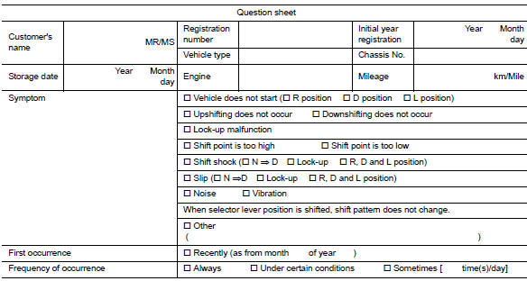
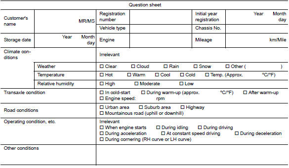
Diagnostic Work Sheet
DESCRIPTION
There are many operating conditions that may cause a malfunction of the transmission parts. By understanding those conditions properly, a quick and exact diagnosis can be achieved.
In general, perception of a problem varies depending on individuals.
Ask the customer about his/her concerns carefully. It is important to understand the phenomenon or status. To systemize all the information for the diagnosis, prepare the question sheet referring to the question points.
In some cases, multiple conditions that appear simultaneously may cause a DTC to be detected.
Worksheet Sample
ADDITIONAL SERVICE WHEN REPLACING TCM
Description
When replacing the TCM, perform the following work.
TCM PROGRAMMING
- Since vehicle specifications are not yet written in a new TCM, it is necessary to write them with CONSULT.
CAUTION:
When replacing TCM, save TCM data on CONSULT before removing TCM.
LOADING AND STORING OF CALIBRATION DATA
- The TCM acquires calibration data (individual characteristic value) of each solenoid that is stored in the ROM assembly (in the control valve). This enables the TCM to perform accurate control. After the TCM is replaced, check that the calibration data is correctly loaded and stored.
CALIBRATION OF G SENSOR
- TCM stores calibration data (inherent characteristic value) of G sensor to provide accurate control. Therefore, it is required to perform calibration of G sensor after the replacement of TCM
CAUTION:
When replacing TCM and transaxle assembly simultaneously, replace transaxle assembly first and then replace TCM.
Work Procedure
1.CHECK NEW TCM PART NUMBER
Check new TCM part number to see whether it is blank TCM or not.
NOTE:
- Part number of blank TCM is 310F6-XXXXX.
- Check the part number when ordering TCM or with the one included in the label on the container box.
Is the new TCM a blank TCM? YES >> GO TO 2.
NO >> GO TO 3.
2.SAVE TCM DATA (VEHICLE SPECIFICATIONS)
 With CONSULT
- Turn ignition switch OFF.
- Turn ignition switch ON.
- Select “Re/programming, Configuration”.
- Select “AT/CVT”.
NOTE:
If “AT/CVT” is not displayed and TCM data cannot be saved on CONSULT, GO TO 3.
- Select “Programming”.
- Save TCM data on CONSULT according to the CONSULT display.
>> GO TO 3.
3.REPLACE TCM
- Turn ignition switch OFF and wait for 10 seconds.
- Replace TCM. Refer to TM-263, "Removal and Installation".
>> GO TO 4.
4.LOAD CALIBRATION DATA
- Shift the selector lever to the “P” position.
- Turn ignition switch ON.
- Check that “P” is displayed on shift position indicator on combination meter.
NOTE:
Displayed approximately 4 – 5 seconds after the selector lever is moved to the “P” position.
Does the shift position indicator display “P”?
YES >> GO TO 5.
NO >> GO TO 8
5.STORE CALIBRATION DATA
- Turn ignition switch OFF and wait for 5 seconds.
- Turn ignition switch ON.
Does the shift position indicator display “P” at the same time when turning ON the ignition switch? YES-1 (New TCM is blank)>>GO TO 6.
YES-2 (New TCM is not blank)>>GO TO 7.
NO >> Check harness between battery and TCM harness connector terminal.
6.WRITE TCM DATA (VEHICLE SPECIFICATIONS)
 With CONSULT
- Select “Programming”.
- Perform programming according to the CONSULT display.
>> GO TO 7.
7.PERFORM CALIBRATION OF G SENSOR
Refer to TM-147, "Work Procedure".
>> WORK END
8.DETECT MALFUNCTIONING ITEM
Check the following items:
- Harness between the TCM and the ROM assembly inside the transaxle assembly is open or shorted.
- Disconnected, loose, bent, collapsed, or otherwise abnormal connector housing terminals
Is the inspection result normal? YES >> GO TO 2.
NO >> Repair or replace the malfunctioning parts.
ADDITIONAL SERVICE WHEN REPLACING TRANSAXLE ASSEMBLY
Description
When replacing the transaxle, perform the following work.
ERASING, LOADING AND STORING OF CALIBRATION DATA
- The TCM acquires calibration data (individual characteristic value) of each solenoid that is stored in the ROM assembly (in the control valve). This enables the TCM to perform accurate control. For this reason, after the transaxle assembly is replaced, it is necessary to erase the calibration data previously stored in TCM, to load new calibration data, and to store them.
ERASING THE LEARNED VALUE DATA
- TCM learns indicated pressure for appropriate control of the transaxle assembly and records the learned values. For this reason, the leaned values stored in TCM must be erased after replacing a transaxle assembly.
ERASING CVT FLUID DEGRADATION LEVEL DATA
- TCM records the degradation level of the CVT fluid calculated from the vehicle driving status. Therefore, if the transaxle assembly is replaced, it is necessary to erase the CVT fluid degradation level data recorded by TCM.
Work Procedure
1.INITIALIZE TCM
 With CONSULT
- Set parking brake.
- Turn ignition switch ON.
- Select “Work Support” in “TRANSMISSION”.
- Select “ERASE MEMORY DATA”.
- While maintaining the conditions below, touch “Start”.
- Vehicle stop status
- With engine stopped
- Selector lever: “R” position
- Accelerator pedal: Depressed
NOTE:
Select “Start” and complete within approximately 20 seconds.
Is “COMPLETED” displayed? YES >> GO TO 2.
NO >> Turn the ignition switch OFF and wait for a minimum of 10 seconds then perform the work again.
2.CHECK AFTER TCM IS INITIALIZED
 With CONSULT
- Turn ignition switch OFF with the selector lever in “R” position and wait for 10 seconds or more.
- Turn ignition switch ON with the selector lever in “R” position.
CAUTION:
Never start the engine.
- Select “Special function” in “TRANSMISSION”.
- Select “CALIB DATA”.
- Check that indicated value of “CALIB DATA” is equal to the value shown in the following table.
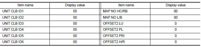
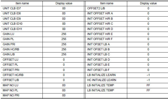
Is the indicated value of “CALIB DATA” equal to the value shown in the table? YES >> GO TO 3.
NO >> GO TO 1.
3.LOAD CALIBRATION DATA
- Shift the selector lever to the “P” position.
- Check that “P” is displayed on shift position indicator on combination meter.
NOTE:
Displayed approximately 4 – 5 seconds after the selector lever is moved to the “P” position.
Does shift position indicator display “P”? YES >> GO TO 5.
NO >> GO TO 4.
4.DETECT MALFUNCTIONING ITEMS
Check the following items:
- Harness between the TCM and the ROM assembly inside the transaxle assembly is open or shorted.
- Disconnected, loose, bent, collapsed, or otherwise abnormal connector housing terminals
Is the inspection result normal? YES >> GO TO 1.
NO >> Repair or replace the malfunctioning parts.
5.STORE CALIBRATION DATA
- Turn ignition switch OFF and wait for 5 seconds.
- Turn ignition switch ON.
Does the shift position indicator display “P” at the same time when turning ON the ignition switch? YES >> GO TO 6.
NO >> Check harness between battery and TCM harness connector terminal.
6.ERASE THE CVT FLUID DEGRADATION LEVEL DATA
 With CONSULT
- Select “WORK SUPPORT” in “TRANSMISSION”.
- Select “CONFORM CVTF DETERIORTN”.
- Touch “Clear”.
>> WORK END
CALIBRATION OF G SENSOR
Description
TCM stores calibration data (inherent characteristic value) of G sensor to provide accurate control. Therefore, it is required to perform calibration of G sensor after the following work is performed.
- Removal/installation or replacement of G sensor
- Replacement of TCM
Work Procedure
1.PREPARATION BEFORE CALIBRATION PROCEDURE
- Park the vehicle on a level surface.
- Adjust air pressure of all tires to the specified pressure. WT-54, "Tire Air Pressure".
>> GO TO 2.
2.PERFORM G SENSOR CALIBRATION
 With CONSULT
- Turn ignition switch ON.
CAUTION:
Never start engine.
- Select “Work Support” in “TRANSMISSION”.
- Select “G SENSOR CALIBRATION”.
- Touch “Start”.
CAUTION:
Never swing the vehicle during “G sensor calibration”.
Is “COMPLETED” displayed? YES >> GO TO 3.
NO >> Perform steps 1 and 2 again.
3.CHECK DTC
 With CONSULT
- Turn ignition switch OFF and wait for 10 seconds.
- Turn ignition switch ON.
- Select “Self Diagnostic Results” in “TRANSMISSION”.
Is “P1586” or “P1588” detected? YES >> Go to TM-126, "DTC Index".
NO >> Calibration end
STALL TEST
Work Procedure
INSPECTION
- Check the engine oil level. Replenish if necessary. Refer to LU-7, "Inspection".
- Check for leak of the CVT fluid. Refer to TM-250, "Inspection".
- Drive for about 10 minutes to warm up the vehicle so that the CVT fluid temperature is 50 to 80В°C (122 to 176В°F).
- Be sure to apply the parking brake and block the tires.
- Start the engine, depress the brake pedal and put the selector lever to the D position.
- While depressing the brake pedal, depress the accelerator pedal gradually.
- Read the stall speed quickly. Then, release your foot from the accelerator pedal quickly.
CAUTION:
Never depress the accelerator pedal for 5 seconds or more during the test.
Stall speed : Refer to TM-288, "Stall Speed".
- Place the selector lever in the N position.
- Cool the CVT fluid.
CAUTION:
Run the engine with the idle speed for at least 1 minute.
- Put the selector lever to the R position and perform Step 6 to Step 9 again.
NARROWING-DOWN MALFUNCTIONING PARTS
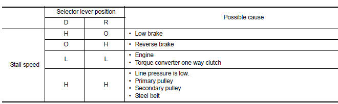
O: Within the stall speed standard value
H: Stall speed is higher than the standard value.
L: Stall speed is lower than the standard value.
LINE PRESSURE TEST
Work Procedure
INSPECTION
- Check the engine oil level. Replenish if necessary. LU-7, "Inspection".
- Check for leak of the CVT fluid. Refer to TM-250, "Inspection".
- Drive for about 10 minutes to warm up the vehicle so that the CVT fluid temperature is 50 to 80В°C (122 to 176В°F).
- Be sure to apply the parking brake and block the tires.
- Start the engine.
- Select “Data Monitor” in “TRANSMISSION”.
- Select “LINE PRESSURE”.
- Measure the line pressure at both idle and the stall speed.
CAUTION:
Keep brake pedal pressed all the way down during measurement.
Line pressure : Refer to TM-289, "Line Pressure".
NARROWING-DOWN MALFUNCTIONING PARTS
| Judgment | Possible cause | |
| Idle speed | Low for all positions (“P”, “R”, “N”, “D”, “L”) | Possible causes include malfunctions in the pressure supply system
and low oil pump output. For example
|
| Only low for a specific position | Possible causes include an oil pressure leak in a passage or device related to the position after the pressure is distributed by the manual valve. | |
| High | Possible causes include a sensor malfunction or malfunction in the
line pressure adjustment
function. For example
|
|
| Stall speed | Line pressure does not rise higher than the line pressure for idle. | Possible causes include a sensor malfunction or malfunction in the
pressure adjustment function. For example
|
| The pressure rises, but does not enter the standard position. | Possible causes include malfunctions in the pressure supply system
and malfunction in the pressure
adjustment function. For example
|
|
| Only low for a specific position | Possible causes include an oil pressure leak in a passage or device related to the position after the pressure is distributed by the manual valve. | |
CVT position
Inspection
INSPECTION
- Turn ON the ignition switch with the shift selector at the “P” position.
- Press the shift selector button with the brake pedal depressed, and confirm that the shift selector can be moved to positions other than “P”. Also confirm that movement is not allowed from the “P” position to other position without depressing the brake pedal.
- Move the shift selector and check for “excessive effort”, “sticking”, “noise” or “rattle”.
- Confirm that shift selector stops at each position with the feel of engagement when it is moved through all the positions. Check whether or not the actual position the shift selector is in matches the position shown by the transaxle body.
- Make sure that the shift selector is moved to all the shift positions in the manner shown.
- (A): Press shift selector button to operate shift selector, while depressing the brake pedal.
- (B): Press shift selector button to operate shift selector.
- (C): Shift selector can be operated without pressing the shift selector button.
- When the shift selector button is pressed without applying forward/ backward force to the shift selector at “P”, “R”, “N”, “D” or “Ds” positions, there should be no “sticking” on the shift selector button operation.
- Check that the back-up lamps do not illuminate when the shift selector is in the “P” position.
- Check that the engine can be started with the shift selector in the “P” and “N” positions only.
- Check that the transaxle is locked completely when the shift selector is in the “P” position.
Adjustment
- Shift the selector lever to the “P” position.
CAUTION:
Rotate the wheels at least a quarter turn and be certain the Park position mechanism is fully engaged.
- Remove nut (A) and set manual lever (B) to the “P” position.
CAUTION:
Do not apply force to the manual lever.
- Tighten nuts to the specified torque. Refer to TM-256, "Exploded View".
CAUTION:
In tightening, fix the manual lever.
HOW TO ERASE PERMANENT DTC
Description
Permanent DTC can be erased by driving each driving pattern.
ECM recognizes each driving pattern; it transmits signals to each control module when the driving is complete.
Each control module erases permanent DTC based on those signals. For details, refer to EC-151, "Description".
 Wiring diagram
CVT Control system
Wiring Diagram
CVT Shift lock system
Wiring Diagram
...
 DTC/Circuit diagnosis
U0073 COMMUNICATION BUS A OFF
DTC Logic
DTC DETECTION LOGIC
DTC
CONSULT screen terms
(Trouble diagnosis content)
DTC detection condition
Possible causes
U0073
COMM BU ...
Other materials:
Service data and specifications (SDS)
Service Data and Specification (SDS)
COMPRESSOR
OIL
REFRIGERANT
...
Cleaning
If your windshield is not clear after using the
windshield washer or if a wiper blade chatters
when running, wax or other material may be on
the blade or windshield.
Clean the outside of the windshield with a washer
fluid or a mild detergent. Your windshield is clean
if beads do not form whe ...
Turn signal switch
Turn signal
Move the lever up or down to signal the
turning direction. When the turn is completed,
the turn signal cancels automatically.
Lane change signal
To signal a lane change, move the lever up or
down to the point where the indicator light
begins to flash, but the lever ...
