Nissan Sentra Service Manual: Preparation
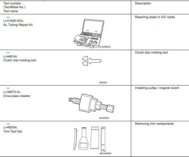
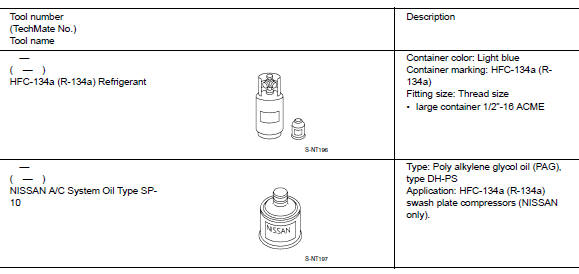
Special service tool
The actual shape of the tools may differ from those illustrated here.
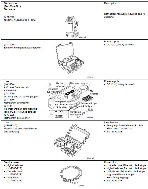
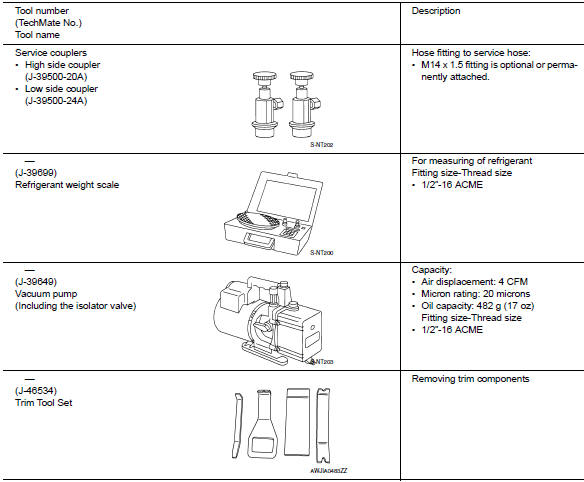
HFC-134a (r-134a) service tool and equipmen.T.
Do not mix HFC-134a (R-134a) refrigerant and/or its specified oil with CFC-12 (R-12) refrigerant and/or its oil.
Separate and non-interchangeable service equipment must be used for handling each type of refrigerant/oil.
Refrigerant container fittings, service hose fittings and service equipment fittings (equipment which handles refrigerant and/or oil) are different between CFC-12 (R-12) and HFC-134a (R-134a). This is to avoid mixed use of the refrigerants/oil.
Adapters that convert one size fitting to another must not be used or refrigerant/oil contamination will occur and compressor failure will result.
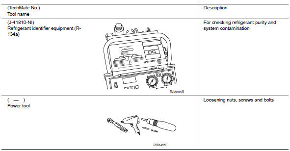
Commercial service tool
Sealant or/and lubricant
 Service equipment
RECOVERY/RECYCLING RECHARGING EQUIPMENT
Be certain to follow the manufacturer’s instructions for machine operation
and machine maintenance. Do not
introduce any refrigerant other than that s ...
 System description
Refrigeration system
Component part location
High-pressure service port
High-pressure pipe
Expansion valve
Low-pressure service port
Low-pressure flexible hose
Compressor
Refrige ...
Other materials:
Unbalance steering wheel turning force (torque variation)
Description
Unbalance steering wheel turning force (torque variation).
Diagnosis Procedure
1.PERFORM SELF-DIAGNOSIS
With CONSULT
Turn the ignition switch OFF to ON.
Perform EPS self-diagnosis.
Is any DTC detected?
YES >> Check the DTC. Refer to STC-14, "DTC Index&quo ...
Rear window glass
Exploded View
Rear window glass
Spacer
Rubber dam
Body side outer
Headlining
Roof panel
Trunk lid
Adhesive
12 mm (0.5 in)
7 mm (0.3 in)
2.0 mm (0.08 in)
3 mm (0.1 in)
Removal and Installation
REMOVAL
Partially remove the rear of the headlining (rear edge). R ...
P0132 A/F SENSOR 1
DTC Logic
DTC DETECTION LOGIC
To judge the malfunction, the diagnosis checks that the A/F signal computed
by ECM from the A/F sensor 1
signal is not inordinately high.
DTC No.
CONSULT screen terms
(Trouble diagnosis content)
DTC detecting condition
Possible cause
P0 ...
