Nissan Sentra B18 (2020-2025) Service Manual: Service Data and Specifications (sds). Service Data and Specifications (sds)
Service Data and Specifications (sds)
General Specification
General Specification
GENERAL SPECIFICATIONS
|
Engine type |
MR20DD |
||||
|
Cylinder arrangement |
In-line 4 |
||||
|
Displacement cm3 (cu in) |
1,997 (121.86) |
||||
|
Bore and stroke mm (in) |
84.0├Ś90.1 (3.307├Ś3.547) |
||||
|
Valve arrangement |
DOHC |
||||
|
Firing order |
1-3-4-2 |
||||
|
Number of piston rings |
Compression |
2 |
|||
|
Oil |
1 |
||||
|
Compression ratio |
10.6 : 1 |
||||
|
Compression pressure kPa (bar, kg/cm2, psi)/250 rpm |
Standard |
1,530 (15.3, 15.6, 222) |
|||
|
Minimum |
1,280 (12.8, 13.1, 186) |
||||
|
Differential limit between cylinders |
100 (1.0, 1.0, 15) |
||||
|
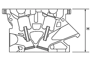
Valve timing
|
VTC Minimum phasing (Mechanical) 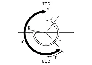
|
VTC Maximum phasing (Mechanical) 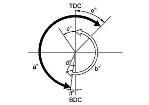
|
||||
|
a EXH valve opening angle |
b INT valve opening angle |
c INT open |
d INT close |
e EXH close |
f EXH open |
|
|
VTC Minimum phasing (Mechanical) |
220 |
240 |
37 |
7 |
0 |
40 |
|
VTC Maximum phasing (Mechanical) |
35 |
25 |
48 |
8 |
||
 :
Exhaust valve
:
Exhaust valve*1: When running at idle with engine coolant temperature more than 60┬░C (140┬░F).
*2: When the intake or exhaust valve opening angle is at the maximum.
*3: When starting the engine with engine coolant temperature 60┬░C (140┬░F) or less.
Spark Plug
Spark Plug
SPARK PLUG
Unit: mm (in)|
Make |
DENSO |
|
|
Standard type |
DXE22H11C |
|
|
Gap (Nominal) |
1.1 (0.043) |
|
Exhaust Manifold
Exhaust Manifold
EXHAUST MANIFOLD
Unit: mm (in)|
Items |
Limit |
|
|
Surface distortion |
Each exhaust port |
0.3 (0.012) |
|
Entire part |
0.7 (0.028) |
|
Camshaft
Camshaft
CAMSHAFT
Unit: mm (in)|
Items |
Standard |
Limit |
|||
|
Camshaft journal oil clearance |
No. 1 |
0.038 - 0.086 (0.0015 - 0.0034) |
0.15 (0.0059) |
||
|
No. 2, 3, 4, 5 |
0.030 - 0.071 (0.0012 - 0.0028) |
||||
|
Camshaft bracket inner diameter |
No. 1 |
28.000 - 28.021 (1.1024 - 1.1032) |
ŌĆö |
||
|
No. 2, 3, 4, 5 |
25.000 - 25.021 (0.9843 - 0.9851) |
ŌĆö |
|||
|
Camshaft journal diameter |
No. 1 |
27.935 - 27.962 (1.0998 - 1.1009) |
ŌĆö |
||
|
No. 2, 3, 4, 5 |
24.950 - 24.970 (0.9823 - 0.9831) |
ŌĆö |
|||
|
Camshaft end play |
0.075 - 0.153 (0.0030 - 0.0060) |
0.24 (0.0094) |
|||
|
Camshaft cam height ŌĆ£AŌĆØ |
Intake |
45.265 - 45.455 (1.7821 - 1.7896) |
45.085 (1.7750) |
||
|
Exhaust |
43.205 - 43.395 (1.7010 - 1.7085) |
43.575 (1.7155) |
|||
|
Camshaft runout [TIR*] |
Less than 0.014 (0.0006) |
0.05 (0.0020) |
|||
|
Camshaft sprocket runout [TIR*] |
ŌĆö |
0.15 (0.0059) |
|||
 |
|||||
*: Total indicator reading
VALVE LIFTER
Unit: mm (in)|
Items |
Standard |
|
|
Valve lifter outer diameter |
Intake |
33.977 - 33.987 (1.3377 - 1.3381) |
|
Exhaust |
29.977 - 29.987 (1.1802 - 1.1806) |
|
|
Valve lifter hole diameter |
Intake |
34.000 - 34.021 (1.3386 - 1.3394) |
|
Exhaust |
30.000 - 30.021 (1.1811 - 1.1819) |
|
|
Valve lifter clearance |
0.013 - 0.044 (0.0005 - 0.0017) |
VALVE CLEARANCE
Unit: mm (in)|
Items |
Cold |
Hot* (reference data) |
|---|---|---|
|
Intake |
0.26 - 0.34 (0.010 - 0.013) |
0.304 - 0.416 (0.012 - 0.016) |
|
Exhaust |
0.27 - 0.36 (0.011 - 0.014) |
0.308 - 0.432 (0.012 - 0.017) |
*: Approximately 80┬░C (176┬░F)
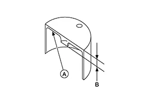
AVAILABLE VALVE LIFTER
Unit: mm (in)|
Identification mark (A) |
Thickness (B) |
|
|---|---|---|
 |
||
|
Intake |
Exhaust |
|
|
300, 00FS, 00fs, 00FB, 00fb |
300, 00JS, 00js, 00JB, 00jb |
3.00 (0.1181) |
|
302, 02FS, 02fs, 02FB, 02fb |
302, 02JS, 02js, 02JB, 02jb |
3.02 (0.1189) |
|
304, 04FS, 04fs, 04FB, 04fb |
304, 04JS, 04js, 04JB, 04jb |
3.04 (0.1197) |
|
306, 06FS, 06fs, 06FB, 06fb |
306, 06JS, 06js, 06JB, 06jb |
3.06 (0.1205) |
|
308, 08FS, 08fs, 08FB, 08fb |
308, 08JS, 08js, 08JB, 08jb |
3.08 (0.1213) |
|
310, 10FS, 10fs, 10FB, 10fb |
310, 10JS, 10js, 10JB, 10jb |
3.10 (0.1220) |
|
312, 12FS, 12fs, 12FB, 12fb |
312, 12JS, 12js, 12JB, 12jb |
3.12 (0.1228) |
|
314, 14FS, 14fs, 14FB, 14fb |
314, 14JS, 14js, 14JB, 14jb |
3.14 (0.1236) |
|
316, 16FS, 16fs, 16FB, 16fb |
316, 16JS, 16js, 16JB, 16jb |
3.16 (0.1244) |
|
318, 18FS, 18fs, 18FB, 18fb |
318, 18JS, 18js, 18JB, 18jb |
3.18 (0.1252) |
|
320, 20FS, 20fs, 20FB, 20fb |
320, 20JS, 20js, 20JB, 20jb |
3.20 (0.1260) |
|
322, 22FS, 22fs, 22FB, 22fb |
322, 22JS, 22js, 22JB, 22jb |
3.22 (0.1268) |
|
324, 24FS, 24fs, 24FB, 24fb |
324, 24JS, 24js, 24JB, 24jb |
3.24 (0.1276) |
|
326, 26FS, 26fs, 26FB, 26fb |
326, 26JS, 26js, 26JB, 26jb |
3.26 (0.1283) |
|
328, 28FS, 28fs, 28FB, 28fb |
328, 28JS, 28js, 28JB, 28jb |
3.28 (0.1291) |
|
330, 30FS, 30fs, 30FB, 30fb |
330, 30JS, 30js, 30JB, 30jb |
3.30 (0.1299) |
|
332, 32FS, 32fs, 32FB, 32fb |
332, 32JS, 32js, 32JB, 32jb |
3.32 (0.1307) |
|
334, 34FS, 34fs, 34FB, 34fb |
334, 34JS, 34js, 34JB, 34jb |
3.34 (0.1315) |
|
336, 36FS, 36fs, 36FB, 36fb |
336, 36JS, 36js, 36JB, 36jb |
3.36 (0.1323) |
|
338, 38FS, 38fs, 38FB, 38fb |
338, 38JS, 38js, 38JB, 38jb |
3.38 (0.1331) |
|
340, 40FS, 40fs, 40FB, 40fb |
340, 40JS, 40js, 40JB, 40jb |
3.40 (0.1339) |
|
342, 42FS, 42fs, 42FB, 42fb |
342, 42JS, 42js, 42JB, 42jb |
3.42 (0.1346) |
|
344, 44FS, 44fs, 44FB, 44fb |
344, 44JS, 44js, 44JB, 44jb |
3.44 (0.1354) |
|
346, 46FS, 46fs, 46FB, 46fb |
346, 46JS, 46js, 46JB, 46jb |
3.46 (0.1362) |
|
348, 48FS, 48fs, 48FB, 48fb |
348, 48JS, 48js, 48JB, 48jb |
3.48 (0.1370) |
|
350, 50FS, 50fs, 50FB, 50fb |
350, 50JS, 50js, 50JB, 50jb |
3.50 (0.1378) |
Cylinder Head
Cylinder Head
CYLINDER HEAD
Unit: mm (in)|
Items |
Standard |
Limit |
|---|---|---|
|
Head surface distortion |
ŌĆö |
0.1 (0.004) |
|
Normal cylinder head height ŌĆ£HŌĆØ |
130.9 (5.15) |
ŌĆö |
 |
VALVE DIMENSIONS
Unit: mm (in)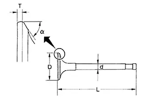 |
||
|
Valve head diameter ŌĆ£DŌĆØ |
Intake |
33.8 - 34.1 (1.331 - 1.343) |
|
Exhaust |
27.6 - 27.9 (1.087 - 1.098) |
|
|
Valve length ŌĆ£LŌĆØ |
Intake |
106.42 (4.19) |
|
Exhaust |
105.41 (4.15) |
|
|
Valve stem diameter ŌĆ£dŌĆØ |
Intake |
5.465 - 5.480 (0.2152 - 0.2157) |
|
Exhaust |
5.455 - 5.470 (0.2148 - 0.2154) |
|
|
Valve seat angle ŌĆ£╬▒ŌĆØ |
45┬░15ŌĆ▓ - 45┬░45ŌĆ▓ |
|
|
Valve margin ŌĆ£TŌĆØ |
Intake |
1.3 - 1.6 (0.051 - 0.063) |
|
Exhaust |
1.45 - 1.75 (0.057 - 0.069) |
|
VALVE GUIDE
Unit: mm (in)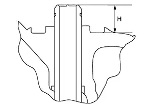 |
||||
|
Items |
Standard |
Oversize (service) [0.2 (0.008)] |
||
|
Valve guide |
Outer diameter |
9.523 - 9.534 (0.3749 - 0.3754) |
9.723 - 9.734 (0.3828 - 0.3832) |
|
|
Inner diameter (Finished size) |
5.500 - 5.518 (0.2165 - 0.2172) |
|||
|
Cylinder head valve guide hole diameter |
9.475 - 9.496 (0.3730 - 0.3739) |
9.675 - 9.696 (0.3809 - 0.3817) |
||
|
Interference fit of valve guide |
0.027 - 0.059 (0.0011 - 0.0023) |
|||
|
Items |
Standard |
Limit |
||
|
Valve guide clearance |
Intake |
0.020 - 0.053 (0.0008 - 0.0021) |
0.1 (0.004) |
|
|
Exhaust |
0.030 - 0.063 (0.0012 - 0.0025) |
|||
|
Projection length ŌĆ£HŌĆØ |
13.35 - 13.65 (0.5256 - 0.5374) |
|||
VALVE SEAT
Unit: mm (in)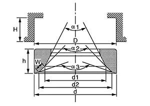 |
|||
|
Items |
Standard |
Oversize (service) [0.5 (0.02)] |
|
|
Cylinder head seat recess diameter ŌĆ£DŌĆØ |
Intake |
34.700 - 34.727 (1.3661 - 1.3672) |
35.200 - 35.227 (1.3858 - 1.3869) |
|
Exhaust |
28.700 - 28.727 (1.1299 - 1.1310) |
29.200 - 29.227 (1.1496 - 1.1507) |
|
|
Valve seat outer diameter ŌĆ£dŌĆØ |
Intake |
34.797 - 34.813 (1.3700 - 1.3706) |
35.297 - 35.313 (1.3896 - 1.3903) |
|
Exhaust |
28.808 - 28.824 (1.1342 - 1.1348) |
29.308 - 29.324 (1.1539 - 1.1545) |
|
|
Valve seat interference fit |
Intake |
0.070 - 0.113 (0.0028 - 0.0044) |
|
|
Exhaust |
0.081 - 0.124 (0.0032 - 0.0049) |
||
|
Diameter ŌĆ£d1ŌĆØ*1 |
Intake |
31.8 (1.252) |
|
|
Exhaust |
25.3 (0.996) |
||
|
Diameter ŌĆ£d2ŌĆØ*2 |
Intake |
33.1 - 33.6 (1.303 - 1.323) |
|
|
Exhaust |
26.9 - 27.4 (1.059 - 1.079) |
||
|
Angle ŌĆ£╬▒1ŌĆØ |
Intake |
70┬░ |
|
|
Exhaust |
45┬░ |
||
|
Angle ŌĆ£╬▒2ŌĆØ |
88┬░45ŌĆ▓ - 90┬░15ŌĆ▓ |
||
|
Angle ŌĆ£╬▒3ŌĆØ |
120┬░ |
||
|
Contacting width ŌĆ£WŌĆØ*3 |
Intake |
1.0 - 1.4 (0.039 - 0.055) |
|
|
Exhaust |
1.2 - 1.6 (0.047 - 0.063) |
||
|
Height ŌĆ£hŌĆØ |
Intake |
5.9 - 6.0 (0.232 - 0.236) |
5.0 - 5.1 (0.197 - 0.201) |
|
Exhaust |
4.95 - 5.05 (0.1949 - 0.1988) |
||
|
Depth ŌĆ£HŌĆØ |
Intake |
6.04 (0.2378) |
|
|
Exhaust |
6.05 (0.2382) |
||
*1: Diameter made by intersection point of conic angles ŌĆ£╬▒1ŌĆØ and ŌĆ£╬▒2ŌĆØ
*2: Diameter made by intersection point of conic angles ŌĆ£╬▒2ŌĆØ and ŌĆ£╬▒3ŌĆØ
*3: Machining data
VALVE SPRING
|
Items |
Standard |
|
|---|---|---|
|
Intake |
Exhaust |
|
|
Free height |
48.5 mm (1.909 in) |
52.0 mm (2.047 in) |
|
Installation height |
37.46 mm (1.475 in) |
37.46 mm (1.475 in) |
|
Installation load |
155 - 171 N (15.8 - 17.4 kg, 34.8 - 38.4 lb) |
140 - 156 N (14.3 - 15.9 kg, 31.5 - 35.1 lb) |
|
Height during valve open |
27.86 mm (1.0968 in) |
29.4 mm (1.1575 in) |
|
Load with valve open |
351 - 385 N (35.8 - 39.3 kg, 78.9 - 86.5 lb) |
280.8 - 306.8 N (28.6 - 31.3 kg, 63.1 - 69.0 lb) |
|
Identification color |
Yellow |
ŌĆö |
|
Items |
Limit |
|
|---|---|---|
|
Valve spring squareness |
1.0 (0.039) |
|
Cylinder Block
Cylinder Block
CYLINDER BLOCK
Unit: mm (in)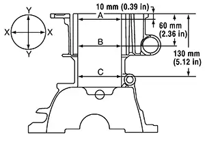 |
||||
|
Cylinder block top surface distortion |
Limit |
0.03 (0.0012) |
||
|
Cylinder bore inner diameter |
Standard |
Grade No. 1 |
84.000 - 84.010 (3.3071 - 3.3075) |
|
|
Grade No. 2 |
84.010 - 84.020 (3.3075 - 3.3079) |
|||
|
Out-of-round |
Limit |
0.015 (0.0006) |
||
|
Taper |
0.010 (0.0004) |
|||
|
Main bearing housing inner diameter grade |
Grade No. A Grade No. B Grade No. C Grade No. D Grade No. E Grade No. F Grade No. G Grade No. H Grade No. J Grade No. K Grade No. L Grade No. M Grade No. N Grade No. P Grade No. R Grade No. S Grade No. T Grade No. U Grade No. V Grade No. W |
55.997 - 55.998 (2.2046 - 2.2046) 55.998 - 55.999 (2.2046 - 2.2047) 55.999 - 56.000 (2.2047 - 2.2047) 56.000 - 56.001 (2.2047 - 2.2048) 56.001 - 56.002 (2.2048 - 2.2048) 56.002 - 56.003 (2.2048 - 2.2048) 56.003 - 56.004 (2.2048 - 2.2049) 56.004 - 56.005 (2.2049 - 2.2049) 56.005 - 56.006 (2.2049 - 2.2050) 56.006 - 56.007 (2.2050 - 2.2050) 56.007 - 56.008 (2.2050 - 2.2050) 56.008 - 56.009 (2.2050 - 2.2051) 56.009 - 56.010 (2.2051 - 2.2051) 56.010 - 56.011 (2.2051 - 2.2052) 56.011 - 56.012 (2.2052 - 2.2052) 56.012 - 56.013 (2.2052 - 2.2052) 56.013 - 56.014 (2.2052 - 2.2053) 56.014 - 56.015 (2.2053 - 2.2053) 56.015 - 56.016 (2.2053 - 2.2053) 56.016 - 56.017 (2.2053 - 2.2054) |
||
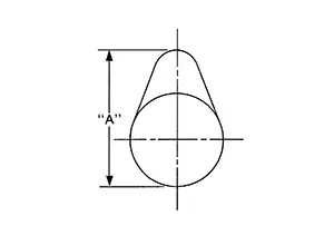
AVAILABLE PISTON
Unit: mm (in)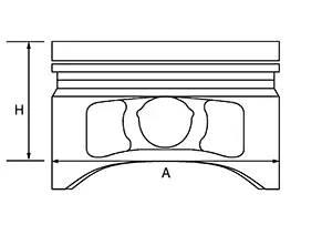 |
|||
|
Piston skirt diameter ŌĆ£AŌĆØ |
Standard |
Grade No. 1 |
83.970 - 83.980 (3.3059 - 3.3063) |
|
Grade No. 2 |
83.980 - 83.990 (3.3063 - 3.3067) |
||
|
Measure point ŌĆ£HŌĆØ |
39.2 (1.543) |
||
|
Piston pin hole diameter |
19.995 - 20.000 (0.7872 - 0.7874) |
||
|
Piston to cylinder bore clearance |
Standard |
0.020 - 0.040 (0.0008 - 0.0016) |
|
|
Limit |
0.08 (0.0031) |
||
PISTON RING
Unit: mm (in)|
Items |
Standard |
Limit |
|
|
Piston ring side clearance |
Top ring |
0.040 - 0.080 (0.0016 - 0.0031) |
0.11 (0.0043) |
|
2nd ring |
0.030 - 0.070 (0.0012 - 0.0028) |
0.10 (0.0039) |
|
|
Oil ring |
0.055 - 0.155 (0.0022 - 0.0061) |
ŌĆö |
|
|
Piston ring end gap |
Top ring |
0.20 - 0.30 (0.0079 - 0.0118) |
0.49 (0.0193) |
|
2nd ring |
0.50 - 0.65 (0.0197 - 0.0256) |
0.81 (0.0319) |
|
|
Oil (rail ring) |
0.15 - 0.45 (0.0059 - 0.0177) |
0.76 (0.0299) |
|
PISTON PIN
Unit: mm (in)|
Items |
Standard |
Limit |
|
Piston pin outer diameter |
19.990 - 19.993 (0.7870 - 0.7871) |
ŌĆö |
|
Piston to piston pin oil clearance |
0.002 - 0.010 (0.0001 - 0.0004) |
ŌĆö |
CONNECTING ROD
Unit: mm (in)|
Center distance |
138.97 - 139.07 (5.47 - 5.48) |
||
|
Bend [per 100 (3.94)] |
Limit |
0.15 (0.0059) |
|
|
Torsion [per 100 (3.94)] |
Limit |
0.30 (0.0118) |
|
|
Connecting rod bushing inner diameter* |
Standard |
20.000 - 20.012 (0.7874 - 0.7879) |
|
|
Connecting rod bushing oil clearance |
Standard |
0.007 - 0.022 (0.0003 - 0.0009) |
|
|
Limit |
0.03 (0.0012) |
||
|
Connecting rod side clearance |
Standard |
0.200 - 0.352 (0.0079 - 0.0139) |
|
|
Limit |
0.4 (0.016) |
||
|
Connecting rod big end diameter grade |
Grade No. A Grade No. B Grade No. C Grade No. D Grade No. E Grade No. F Grade No. G Grade No. H Grade No. J Grade No. K Grade No. L Grade No. M Grade No. N |
47.000 - 47.001 (1.8504 - 1.8504) 47.001 - 47.002 (1.8504 - 1.8505) 47.002 - 47.003 (1.8505 - 1.8505) 47.003 - 47.004 (1.8505 - 1.8505) 47.004 - 47.005 (1.8505 - 1.8506) 47.005 - 47.006 (1.8506 - 1.8506) 47.006 - 47.007 (1.8506 - 1.8507) 47.007 - 47.008 (1.8507 - 1.8507) 47.008 - 47.009 (1.8507 - 1.8507) 47.009 - 47.010 (1.8507 - 1.8508) 47.010 - 47.011 (1.8508 - 1.8508) 47.011 - 47.012 (1.8508 - 1.8509) 47.012 - 47.013 (1.8509 - 1.8509) |
|
*: After installing in connecting rod
CRANKSHAFT
Unit: mm (in)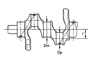 |
 |
|||
|
Center distance ŌĆ£rŌĆØ |
44.89 - 44.97 (1.7673 - 1.7705) |
|||
|
Out-of-round |
Limit |
0.003 (0.0001) |
||
|
Taper |
Limit |
0.01 (0.0004) |
||
|
Runout [TIR*] |
Standard |
0.0035 (0.0001) |
||
|
Limit |
0.1 (0.004) |
|||
|
Crankshaft end play |
Standard |
0.098 - 0.26 (0.0039 - 0.0102) |
||
|
Limit |
0.3 (0.012) |
|||
|
Crankshaft pin journal diameter ŌĆ£DpŌĆØ grade. |
Grade No. A Grade No. B Grade No. C Grade No. D Grade No. E Grade No. F Grade No. G Grade No. H Grade No. J Grade No. K Grade No. L Grade No. M Grade No. N Grade No. P Grade No. R Grade No. S Grade No. T Grade No. U |
43.970 - 43.971 (1.7311 - 1.7311) 43.969 - 43.970 (1.7311 - 1.7311) 43.968 - 43.969 (1.7310 - 1.7311) 43.967 - 43.968 (1.7310 - 1.7310) 43.966 - 43.967 (1.7309 - 1.7310) 43.965 - 43.966 (1.7309 - 1.7309) 43.964 - 43.965 (1.7309 - 1.7309) 43.963 - 43.964 (1.7308 - 1.7309) 43.962 - 43.963 (1.7308 - 1.7308) 43.961 - 43.962 (1.7307 - 1.7308) 43.960 - 43.961 (1.7307 - 1.7307) 43.959 - 43.960 (1.7307 - 1.7307) 43.958 - 43.959 (1.7306 - 1.7307) 43.957 - 43.958 (1.7306 - 1.7306) 43.956 - 43.957 (1.7305 - 1.7306) 43.955 - 43.956 (1.7305 - 1.7305) 43.954 - 43.955 (1.7305 - 1.7305) 43.953 - 43.954 (1.7304 - 1.7305) |
||
|
Crankshaft main journal diameter ŌĆ£DmŌĆØ grade. |
Grade No. A Grade No. B Grade No. C Grade No. D Grade No. E Grade No. F Grade No. G Grade No. H Grade No. J Grade No. K Grade No. L Grade No. M Grade No. N Grade No. P Grade No. R Grade No. S Grade No. T Grade No. U Grade No. V Grade No. W |
51.978 - 51.979 (2.0464 - 2.0464) 51.977 - 51.978 (2.0463 - 2.0464) 51.976 - 51.977 (2.0463 - 2.0463) 51.975 - 51.976 (2.0463 - 2.0463) 51.974 - 51.975 (2.0462 - 2.0463) 51.973 - 51.974 (2.0462 - 2.0462) 51.972 - 51.973 (2.0461 - 2.0462) 51.971 - 51.972 (2.0461 - 2.0461) 51.970 - 51.971 (2.0461 - 2.0461) 51.969 - 51.970 (2.0460 - 2.0461) 51.968 - 51.969 (2.0460 - 2.0460) 51.967 - 51.968 (2.0459 - 2.0460) 51.966 - 51.967 (2.0459 - 2.0459) 51.965 - 51.966 (2.0459 - 2.0459) 51.964 - 51.965 (2.0458 - 2.0459) 51.963 - 51.964 (2.0458 - 2.0458) 51.962 - 51.963 (2.0457 - 2.0458) 51.961 - 51.962 (2.0457 - 2.0457) 51.960 - 51.961 (2.0457 - 2.0457) 51.959 - 51.960 (2.0456 - 2.0457) |
||
*: Total indicator reading
Connecting Rod Bearing
Connecting Rod Bearing
CONNECTING ROD BEARING GRADE TABLE
Unit: mm (in)|
Grade number |
Thickness ŌĆā |
Identification color |
Remarks |
|
|
0 |
1.494 - 1.497 (0.0588 - 0.0589) |
Black - Black |
Grade and color are the same for upper and lower bearings. |
|
|
1 |
1.497 - 1.500 (0.0589 - 0.0591) |
Brown - Brown |
||
|
2 |
1.500 - 1.503 (0.0591 - 0.0592) |
Green - Green |
||
|
3 |
1.503 - 1.506 (0.0592 - 0.0593) |
Yellow - Yellow |
||
|
4 |
1.506 - 1.509 (0.0593 - 0.0594) |
Blue - Blue |
||
|
01 |
UPR |
1.494 - 1.497 (0.0588 - 0.0589) |
Black - Black |
Grade and color are different between upper and lower bearings. |
|
LWR |
1.497 - 1.500 (0.0589 - 0.0591) |
Brown - Brown |
||
|
12 |
UPR |
1.497 - 1.500 (0.0589 - 0.0591) |
Brown - Brown |
|
|
LWR |
1.500 - 1.503 (0.0591 - 0.0592) |
Green - Green |
||
|
23 |
UPR |
1.500 - 1.503 (0.0591 - 0.0592) |
Green - Green |
|
|
LWR |
1.503 - 1.506 (0.0592 - 0.0593) |
Yellow - Yellow |
||
|
34 |
UPR |
1.503 - 1.506 (0.0592 - 0.0593) |
Yellow - Yellow |
|
|
LWR |
1.506 - 1.509 (0.0593 - 0.0594) |
Blue - Blue |
||
UNDERSIZE TABLE
Unit: mm (in)|
Items |
Thickness |
Crank pin journal diameter |
|
US 0.25 (0.0098) |
1.623 - 1.631 (0.0639 - 0.0642) |
Grind so that bearing clearance is the specified value. |
CONNECTING ROD BEARING OIL CLEARANCE
Unit: mm (in)|
Connecting rod bearing oil clearance |
Standard |
0.037 - 0.047 (0.0015 - 0.0019) |
|
|
Limit |
0.07 (0.0028) |
||
Main Bearing
Main Bearing
MAIN BEARING GRADE TABLE (ALL JOURNALS)
Unit: mm (in)|
Grade number |
Thickness |
Identification color |
Remarks |
|
|
0 |
1.996 - 1.999 (0.0786 - 0.0787) |
Black - Black |
Grade and color are the same for upper and lower bearings. |
|
|
1 |
1.999 - 2.002 (0.0787 - 0.0788) |
Brown - Brown |
||
|
2 |
2.002 - 2.005 (0.0788 - 0.0789) |
Green - Green |
||
|
3 |
2.005 - 2.008 (0.0789 - 0.0791) |
Yellow - Yellow |
||
|
4 |
2.008 - 2.011 (0.0791 - 0.0792) |
Blue - Blue |
||
|
5 |
2.011 - 2.014 (0.0792 - 0.0793) |
Pink - Pink |
||
|
6 |
2.014 - 2.017 (0.0793 - 0.0794) |
Purple - Purple |
||
|
7 |
2.017 - 2.020 (0.0794 - 0.0795) |
White - White |
||
|
01 |
UPR |
1.996 - 1.999 (0.0786 - 0.0787) |
Black - Black |
Grade and color are different between upper and lower bearings. |
|
LWR |
1.999 - 2.002 (0.0787 - 0.0788) |
Brown - Brown |
||
|
12 |
UPR |
1.999 - 2.002 (0.0787 - 0.0788) |
Brown - Brown |
|
|
LWR |
2.002 - 2.005 (0.0788 - 0.0789) |
Green - Green |
||
|
23 |
UPR |
2.002 - 2.005 (0.0788 - 0.0789) |
Green - Green |
|
|
LWR |
2.005 - 2.008 (0.0789 - 0.0791) |
Yellow - Yellow |
||
|
34 |
UPR |
2.005 - 2.008 (0.0789 - 0.0791) |
Yellow - Yellow |
|
|
LWR |
2.008 - 2.011 (0.0791 - 0.0792) |
Blue - Blue |
||
|
45 |
UPR |
2.008 - 2.011 (0.0791 - 0.0792) |
Blue - Blue |
|
|
LWR |
2.011 - 2.014 (0.0792 - 0.0793) |
Pink - Pink |
||
|
56 |
UPR |
2.011 - 2.014 (0.0792 - 0.0793) |
Pink - Pink |
|
|
LWR |
2.014 - 2.017 (0.0793 - 0.0794) |
Purple - Purple |
||
|
67 |
UPR |
2.014 - 2.017 (0.0793 - 0.0794) |
Purple - Purple |
|
|
LWR |
2.017 - 2.020 (0.0794 - 0.0795) |
White - White |
||
UNDERSIZE TABLE
Unit: mm (in)|
Items |
Thickness |
Main journal diameter |
|
US 0.25 (0.0098) |
2.126 - 2.134 (0.0837 - 0.0840) |
Grind so that bearing clearance is the specified value. |
MAIN BEARING OIL CLEARANCE
Unit: mm (in)|
Main bearing oil clearance |
Standard |
0.015 - 0.025 (0.0006 - 0.001) |
|
|
Limit |
0.065 (0.0026) |
||
Other materials:
Component Parts. Interior Lighting System
Interior Lighting System
Component Parts Location
Component Parts
Location
A.
View of instrument panel
B.
Fuse block (J ...
P061b Ecm
Dtc Description
DTC Description
DTC DETECTION LOGIC
DTC
CONSULT screen terms
(Trouble diagnosis
content)
DTC detection
condition
...
B0012-55 Active Vent
Dtc Description
DTC Description
DTC DETECTION LOGIC
DTC No.
CONSULT screen items
(Trouble diagnosis
content)
DTC Detection Condition
...