Nissan Sentra B18 (2020-2025) Service Manual: Secondary Speed Sensor Circuit
Diagnosis Procedure
Diagnosis Procedure
-
CHECK HARNESS CONNECTOR - 1
-
Ignition switch OFF.
-
Check the mating condition of TCM harness connector and secondary speed sensor harness connector.
Is the inspection result normal?
YES >>GO TO 2.
NO >>Repair or replace damaged parts.
-
-
CHECK CONNECTOR TERMINAL - 1
-
Disconnect TCM harness connector and secondary speed sensor harness connector.
-
Check the connectors of TCM and secondary speed sensor for water intrusion, or damage or corrosion of the terminals.
Is the inspection result normal?
YES >>GO TO 3.
NO >>Repair or replace damaged parts.
-
-
CHECK DETECTED DTC
Are primary speed sensor malfunction detected in addition to secondary speed sensor?
YES >>GO TO 4.
NO >>GO TO 10.
-
CHECK SENSOR GROUND CIRCUIT - 1
-
Connect TCM harness connector.
-
Check continuity (resistance) between secondary speed sensor harness connector terminal and ground.
Secondary speed sensor
ŌĆö
Continuity (Resistance)
Connector
Terminal
F54
2
Ground
Existed (1 ╬® or less)
Is the inspection result normal?
YES >>GO TO 6.
NO >>GO TO 5.
-
-
CHECK SENSOR GROUND CIRCUIT - 2
-
Disconnect TCM harness connector.
-
Check continuity (resistance) between TCM harness connector terminal and secondary speed sensor harness connector terminal.
TCM
Secondary speed sensor
Continuity (Resistance)
Connector
Terminal
Connector
Terminal
F23
11
F54
2
Existed (1 ╬® or less)
Is the inspection result normal?
YES >>GO TO 6.
NO >>Repair harness or connector.
-
-
CHECK SENSOR POWER SUPPLY CIRCUIT - 1
-
Connect TCM harness connector.
-
Ignition switch ON.
- Check voltage between secondary speed
sensor harness connector terminal and ground.
+
ŌłÆ
Voltage (Approx.)
Secondary speed sensor
Connector
Terminal
F54
3
Ground
5 V
Is the inspection result normal?
YES >>GO TO 9.
NO >>GO TO 7.
-
-
CHECK SENSOR POWER SUPPLY CIRCUIT - 2
-
Ignition switch OFF.
-
Disconnect TCM harness connector.
-
Check continuity (resistance) between TCM harness connector terminal and secondary speed sensor harness connector terminal.
TCM
Secondary speed sensor
Continuity (Resistance)
Connector
Terminal
Connector
Terminal
F23
36
F54
3
Existed (1 ╬® or less)
Is the inspection result normal?
YES >>GO TO 8.
NO >>Repair harness or connector.
-
-
CHECK SENSOR POWER SUPPLY CIRCUIT - 3
-
Ignition switch ON
-
Check voltage between TCM harness connector terminal and ground.
+
ŌłÆ
Voltage (Approx.)
TCM
Connector
Terminal
F23
36
Ground
0 V
Is the inspection result normal?
YES >>GO TO 9.
NO >>Repair harness.
-
-
CHECK TCM POWER SUPPLY AND GROUND CIRCUITS
Check TCM power supply and ground circuits. Refer to Diagnosis Procedure.
Is the inspection result normal?
YES >>INSPECTION END
NO >>Repair or replace damaged parts.
-
CHECK SECONDARY SPEED SENSOR SIGNAL CIRCUIT
Check continuity (resistance) between TCM harness connector terminal and secondary speed sensor harness connector terminal.
TCM
Secondary speed sensor
Continuity (Resistance)
Connector
Terminal
Connector
Terminal
F23
34
F54
1
Existed (1 ╬® or less)
Is the inspection result normal?
YES >>GO TO 11.
NO >>Repair harness or connector.
-
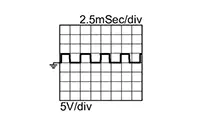
CHECK TCM INPUT SIGNAL (SECONDARY SPEED SENSOR SIGNAL)
-
Connect TCM harness connector and secondary speed sensor harness connector.
-
Start the engine.
-
Check frequency between TCM harness connector terminal and ground.
TCM
ŌłÆ
Test condition
Frequency
Connector
Terminal
F23
34
Ground
-
Accelerator pedal position: 0.5/8
-
Shift position: ŌĆ£LŌĆØ position
-
Nissan Sentra Vehicle speed: 20 km/h (12 MPH)
600 Hz
-
Is the inspection result normal?
YES >>INSPECTION END
NO >>Replace secondary speed sensor. Refer to Removal and Installation.
-
Other materials:
Fuel Level Sensor Unit, Fuel Filter and Fuel Pump Assembly
Exploded View
Exploded View
1.
Lock ring
2.
Fuel level sensor, fuel filter
and fuel pump assembly
...
B0012-55 Active Vent
Dtc Description
DTC Description
DTC DETECTION LOGIC
DTC No.
CONSULT screen items
(Trouble diagnosis
content)
DTC Detection Condition
...
P2135 Tp Sensor
Dtc Description
DTC Description
DTC DETECTION LOGIC
DTC
CONSULT screen terms
(Trouble diagnosis
content)
DTC detection
condition
...