Nissan Sentra B18 (2020-2025) Service Manual: Primary Speed Sensor Circuit
Diagnosis Procedure
Diagnosis Procedure
-
CHECK HARNESS CONNECTOR - 1
-
Ignition switch OFF.
-
Check the mating condition of TCM harness connector and primary speed sensor harness connector.
Is the inspection result normal?
YES >>GO TO 2.
NO >>Repair or replace damaged parts.
-
-
CHECK CONNECTOR TERMINAL - 1
-
Disconnect TCM harness connector and primary speed sensor harness connector.
-
Check the connectors of TCM and primary speed sensor for water intrusion, or damage or corrosion of the terminals.
Is the inspection result normal?
YES >>GO TO 3.
NO >>Repair or replace damaged parts.
-
-
CHECK DETECTED DTC
Are secondary speed sensor malfunction detected in addition to primary speed sensor?
YES >>GO TO 4.
NO >>GO TO 10.
-
CHECK SENSOR GROUND CIRCUIT - 1
-
Connect TCM harness connector.
-
Check continuity (resistance) between primary speed sensor harness connector terminal and ground.
Primary speed sensor
ŌĆö
Continuity (Resistance)
Connector
Terminal
F55
2
Ground
Existed (1 ╬® or less)
Is the inspection result normal?
YES >>GO TO 6.
NO >>GO TO 5.
-
-
CHECK SENSOR GROUND CIRCUIT - 2
-
Disconnect TCM harness connector.
-
Check continuity (resistance) between TCM harness connector terminal and primary speed sensor harness connector terminal.
TCM
Primary speed sensor
Continuity (Resistance)
Connector
Terminal
Connector
Terminal
F23
11
F55
2
Existed (1 ╬® or less)
Is the inspection result normal?
YES >>GO TO 6.
NO >>Repair harness or connector.
-
-
CHECK SENSOR POWER SUPPLY CIRCUIT - 1
-
Connect TCM harness connector.
-
Ignition switch ON.
-
Check voltage between primary speed sensor harness connector terminal and ground.
+
ŌłÆ
Voltage (Approx.)
Primary speed sensor
Connector
Terminal
F55
3
Ground
5 V
Is the inspection result normal?
YES >>GO TO 10.
NO >>GO TO 7.
-
-
CHECK SENSOR POWER SUPPLY CIRCUIT - 2
-
Ignition switch OFF.
-
Disconnect TCM harness connector.
-
Check continuity (resistance) between TCM harness connector terminal and primary speed sensor harness connector terminal.
TCM
Primary speed sensor
Continuity (Resistance)
Connector
Terminal
Connector
Terminal
F23
36
F55
3
Existed (1 ╬® or less)
Is the inspection result normal?
YES >>GO TO 8.
NO >>Repair harness or connector.
-
-
CHECK SENSOR POWER SUPPLY CIRCUIT - 3
-
Ignition switch ON.
-
Check voltage between TCM harness connector terminal and ground.
+
ŌłÆ
Voltage (Approx.)
TCM
Connector
Terminal
F23
36
Ground
0 V
Is the inspection result normal?
YES >>GO TO 9.
NO >>Repair harness.
-
-
CHECK TCM POWER SUPPLY AND GROUND CIRCUITS
Check TCM power supply and ground circuits. Refer to Diagnosis Procedure.
Is the inspection result normal?
YES >>INSPECTION END
NO >>Repair or replace damaged parts.
-
CHECK PRIMARY SPEED SENSOR SIGNAL CIRCUIT
Check continuity (resistance) between TCM harness connector terminal and primary speed sensor harness connector terminal.
TCM
Primary speed sensor
Continuity (Resistance)
Connector
Terminal
Connector
Terminal
F23
35
F55
1
Existed (1 ╬® or less)
Is the inspection result normal?
YES >>GO TO 11.
NO >>Repair harness or connector.
-
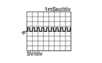
CHECK TCM INPUT SIGNAL (PRIMARY SPEED SENSOR SIGNAL)
-
Connect TCM harness connector and primary speed sensor harness connector.
-
Start the engine.
-
Check frequency between TCM harness connector terminal and ground.
TCM
ŌĆö
Test condition
Frequency
Connector
Terminal
F23
35
Ground
-
Accelerator pedal position: 0.5/8
-
Shift position: ŌĆ£LŌĆØ position
-
Nissan Sentra Vehicle speed: 20 km/h (12 MPH)
1050 Hz
-
Is the inspection result normal?
YES >>INSPECTION END
NO >>Replace primary speed sensor. Refer to Removal and Installation.
-
Other materials:
C1714-7b Low Tire Pressure Rr
Dtc Description
DTC Description
Note:
The Signal Tech II Tool [ŌĆō (NI-50190)] can be used
to perform the following functions: Refer to the Signal Tech II User
Guide for additional information.
Activate and display TPMS sensor IDs
Display tire pressure rep ...
The System Does Not Detect the Vehicle Ahead at All
Diagnosis Procedure
Diagnosis Procedure
When AEB system is active, the AEB system does not perform any
control even though there is a vehicle ahead.
CHECK INFORMATION DISPLAY
Start the ŌĆ£Self DiagnosisŌĆØ
of combination meter. Refer to De ...
Unit Removal and Installation. Transaxle Assembly
Transaxle Assembly
Exploded View
Exploded View
1.
CVT fluid charging pipe cap
2.
CVT fluid charging pipe
...