Nissan Sentra B18 (2020-2025) Service Manual: Input Speed Sensor Circuit
Diagnosis Procedure
Diagnosis Procedure
-
CHECK HARNESS CONNECTOR - 1
-
Ignition switch OFF.
-
Check the mating condition of TCM harness connector and CVT unit harness connector.
Is the inspection result normal?
YES >>GO TO 2.
NO >>Repair or replace damaged parts.
-
-
CHECK CONNECTOR TERMINAL - 1
-
Disconnect TCM harness connector and CVT unit harness connector.
-
Check the connectors of TCM and CVT unit for water intrusion, or damage or corrosion of the terminals.
Is the inspection result normal?
YES >>GO TO 3.
NO >>Repair or replace damaged parts.
-
-
CHECK DETECTED DTC
Are other sensor malfunctions detected in addition to input speed sensor?
YES >>GO TO 4.
NO >>GO TO 10.
-
CHECK SENSOR GROUND CIRCUIT - 1
-
Connect TCM harness connector.
-
Check continuity (resistance) between CVT unit harness connector terminal and ground.
CVT unit
ŌĆö
Continuity (Resistance)
Connector
Terminal
F46
18
Ground
Existed (1 ╬® or less)
Is the inspection result normal?
YES >>GO TO 6.
NO >>GO TO 5.
-
-
CHECK SENSOR GROUND CIRCUIT - 2
-
Disconnect TCM harness connector.
-
Check continuity (resistance) between TCM harness connector terminal and CVT unit harness connector terminal.
TCM
CVT unit
Continuity (Resistance)
Connector
Terminal
Connector
Terminal
F23
15
F46
18
Existed (1 ╬® or less)
Is the inspection result normal?
YES >>GO TO 6.
NO >>Repair harness or connector.
-
-
CHECK SENSOR POWER SUPPLY CIRCUIT - 1
-
If TCM harness connector is disconnected, connect it.
-
Ignition switch ON.
-
Check voltage between CVT unit harness connector terminal and ground.
+
ŌłÆ
Voltage (Approx.)
CVT unit
Connector
Terminal
F46
22
Ground
5 V
Is the inspection result normal?
YES >>GO TO 10.
NO >>GO TO 7.
-
-
CHECK SENSOR POWER SUPPLY CIRCUIT - 2
-
Ignition switch OFF.
-
Disconnect TCM harness connector.
-
Check continuity (resistance) between TCM harness connector terminal and CVT unit harness connector terminal.
TCM
CVT unit
Continuity (Resistance)
Connector
Terminal
Connector
Terminal
F23
26
F46
22
Existed (1 ╬® or less)
Is the inspection result normal?
YES >>GO TO 8.
NO >>Repair harness or connector.
-
-
CHECK SENSOR POWER SUPPLY CIRCUIT - 3
-
Ignition switch ON.
-
Check voltage between TCM harness connector terminal and ground.
+
ŌłÆ
Voltage (Approx.)
TCM
Connector
Terminal
F23
26
Ground
0 V
Is the inspection result normal?
YES >>GO TO 9.
NO >>Repair harness.
-
-
CHECK TCM POWER SUPPLY AND GROUND CIRCUITS
Check TCM power supply and ground circuits. Refer to Diagnosis Procedure.
Is the inspection result normal?
YES >>INSPECTION END
NO >>Repair or replace damaged parts.
-
CHECK INPUT SPEED SENSOR SIGNAL CIRCUIT
Check continuity (resistance) between TCM harness connector terminal and CVT unit harness connector terminal.
TCM
CVT unit
Continuity (Resistance)
Connector
Terminal
Connector
Terminal
F23
24
F46
17
Existed (1 ╬® or less)
Is the inspection result normal?
YES >>GO TO 11.
NO >>Repair harness or connector.
-
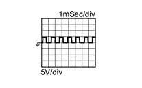
CHECK TCM INPUT SIGNAL (INPUT SPEED SENSOR SIGNAL)
-
Connect TCM harness connector and CVT unit harness connector.
-
Start the engine.
-
Check frequency between TCM harness connector terminal and ground.
TCM
ŌĆö
Test condition
Frequency
Connector
Terminal
F23
24
Ground
-
Accelerator pedal position: 0.5/8
-
Shift position: ŌĆ£LŌĆØ position
-
Nissan Sentra Vehicle speed: 20 km/h (12 MPH)
1050 Hz
-
Is the inspection result normal?
YES >>INSPECTION END
NO >>GO TO 12.
-
-
CHECK HARNESS CONNECTOR - 2
-
Remove transaxle assembly from Nissan Sentra vehicle. Refer to Removal and Installation.
-
Disassemble transaxle assembly to check input speed sensor harness connector. Refer to Disassembly and Assembly.
-
Check the mating condition of input speed sensor harness connector.
Is the inspection result normal?
YES >>GO TO 13.
NO >>Repair or replace damaged parts.
-
-
CHECK CONNECTOR TERMINAL - 2
-
Disconnect input speed sensor harness connector.
-
Check input speed sensor harness connector for damage of the terminals.
Is the inspection result normal?
YES >>GO TO 14.
NO >>Repair or replace damaged parts.
-
-
CHECK INPUT SPEED SENSOR CIRCUIT - 1
-
Remove control valve cover. Refer to Removal and Installation.
CAUTION:
Never disconnect harness connector F102 inside the CVT unit. Refer to Wiring Diagram.
-
Check continuity (resistance) between CVT unit connector terminals and input speed sensor harness connector terminals.
CVT unit
Input speed sensor
Continuity (Resistance)
Terminal
Connector
Terminal
17
F105
2
Existed (1 ╬® or less)
18
1
22
3
Is the inspection result normal?
YES >>Replace input speed sensor. Refer to Disassembly and Assembly.
NO >>GO TO 15.
-
-
CHECK HARNESS CONNECTOR - 3
Check the mating condition of CVT fluid temperature sensor/input speed sensor harness connector.
Is the inspection result normal?
YES >>GO TO 16.
NO >>Repair or replace damaged parts.
-
CHECK CONNECTOR TERMINAL - 3
-
Disconnect CVT fluid temperature sensor/input speed sensor harness connector.
-
Check CVT fluid temperature sensor/input speed sensor harness connector for damage of the terminals.
Is the inspection result normal?
YES >>GO TO 17.
NO >>Repair or replace damaged parts.
-
-
CHECK INPUT SPEED SENSOR CIRCUIT - 2
Check continuity (resistance) between CVT fluid temperature sensor/input speed sensor harness connector terminals and input speed sensor harness connector terminals.
CVT fluid temperature sensor/input speed sensor
Input speed sensor
Continuity (Resistance)
Connector
Terminal
Connector
Terminal
F104
3
F105
3
Existed (1 ╬® or less)
4
2
5
1
Is the inspection result normal?
YES >>GO TO 18.
NO >>Replace CVT fluid temperature sensor (with input speed sensor harness). Refer to Disassembly and Assembly.
-
CHECK INPUT SPEED SENSOR CIRCUIT - 3
Check continuity (resistance) between CVT unit connector terminals and CVT fluid temperature sensor/input speed sensor harness connector terminals.
CVT unit
CVT fluid temperature sensor/input speed sensor
Continuity (Resistance)
Terminal
Connector
Terminal
17
F103
4
Existed (1 ╬® or less)
18
5
22 3
Is the inspection result normal?
YES >>INSPECTION END
NO >>Replace control valve due to harness connector malfunction. Refer to Removal and Installation.
Other materials:
Ventilation System. Periodic Maintenance. In-Cabin Microfilter
In-Cabin Microfilter
Exploded View
Exploded View
1.
Heating and cooling unit
assembly
2.
In-cabin microfilter
...
Engine Mounting Insulator (rh)
Exploded View
Exploded View
CVT Models
1.
Engine mounting
insulator (LH)
2.
Engine mounting
insula ...
Precaution. Precautions
Precautions
Precaution for Supplemental Restraint System (srs) "air Bag" and "seat Belt Pre-Tensioner"
Precaution for Supplemental Restraint System (SRS) "AIR BAG" and "SEAT BELT PRE-TENSIONER"
The Supplemental Restraint System such as
ŌĆ£AIR BAGŌĆØ and ŌĆ£SEAT BELT PRE-TENSIONERŌĆØ,
u ...