Nissan Sentra B18 (2020-2025) Service Manual: Removal and Installation
CVT MODELS
REMOVAL
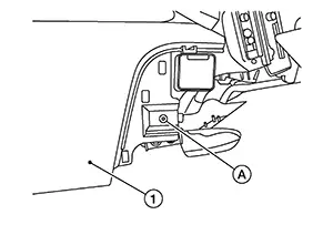
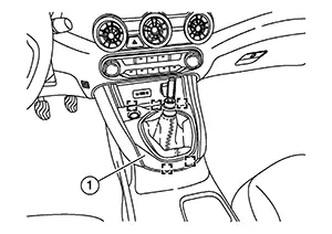
Using a suitable tool, release clips
and remove the center console side finishers [1 (LH/RH)].
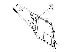 Note:
Note: 
LH shown; RH similar
 : Clip
Remove shift selector finisher using the following steps:
-
Remove the CVT shift selector knob. Refer to Removal & Installation.
-
Using a suitable tool, release clips and pawls.
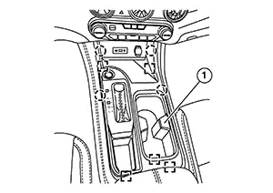
 : Pawl
 : Metal clip
 - Disconnect harness connectors and remove the shift selector finisher (1).
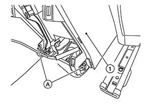
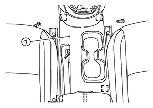
Using a suitable tool, release clips
from center console rear finisher (1).
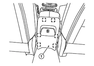
: Metal clip
Disconnect harness connector (if equipped) and remove the center console rear finisher.
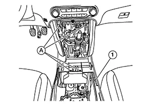
Remove the screws (A).
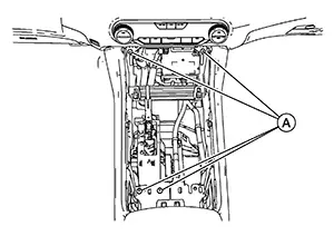
Remove screws [A (LH/RH)] from the
center console assembly (1).
 Note:
Note:
RH shown; LH similar
Remove screws (A) from the center
console assembly (1).
Disconnect harness connectors and remove center console assembly.
INSTALLATION
Installation is in the reverse order of removal.
M/T MODELS
REMOVAL
Using a suitable tool, release clips
and remove the center console side finishers [1 (LH/RH)].
Note:
LH shown; RH similar
: Clip
Remove shift selector finisher using the following steps:
-
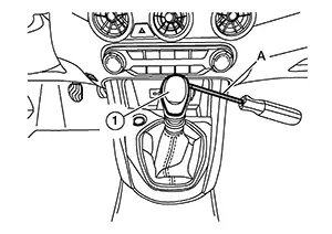
Using suitable tool (A), remove shift knob finisher (1).
-
Remove shift knob (1) as shown.
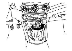
Using a suitable tool, release clips
of shift selector finisher (1).
: Metal clip
Disconnect harness connector and remove shift selector finisher.
Using a suitable tool, release clips
and remove center console cup holder finisher (1).
: Metal clip
Using a suitable tool, release clips
of center console rear finisher (1).
: Metal clip
Disconnect harness connector (if equipped) and remove center console rear finisher (1).
Remove screws (A) from center console
assembly (1).
Remove screws [A (LH/RH)] from center
console assembly (1).
Note:
RH shown; LH similar
Remove screws (A) from center console
assembly (1).
Disconnect harness connectors and remove center console assembly.
INSTALLATION
Installation is in the reverse order of removal.
 Exploded View
Exploded View
CVT MODELS
1.
Shift selector finisher
(CVT)
...

Other materials:
Basic inspection
Diagnosis and repair workflow
Workflow
OVERALL SEQUENCE
DETAILED FLOW
1.INTERVIEW CUSTOMER
Interview the customer to obtain as much information as possible about the
conditions and environment under
which the malfunction occurred.
>> GO TO 2.
2.SYMPTOM CHECK
Verify symptoms.
...
Component Inspection
Component Inspection
CHECK HEATED STEERING WHEEL CONTINUITY
Check continuity between heated steering wheel
connector terminals.
...
Can communication circuit
Diagnosis procedure
1.Connector inspection
Turn the ignition switch off.
Disconnect the battery cable from the negative terminal.
Disconnect all the unit connectors on CAN communication system.
Check terminals and connectors for damage, bend and loose connection.
Is the inspection resu ...
