Nissan Sentra Service Manual: Basic inspection
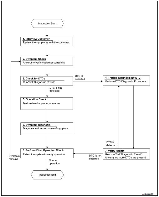
Diagnosis and repair workflow
Workflow
OVERALL SEQUENCE

DETAILED FLOW
1.INTERVIEW CUSTOMER
Interview the customer to obtain as much information as possible about the conditions and environment under which the malfunction occurred.
>> GO TO 2.
2.SYMPTOM CHECK
Verify symptoms.
>> GO TO 3.
3.CHECK FOR DTCS
 With CONSULT
- Turn ignition switch ON.
- Select “Self Diagnostic Result” mode of “HVAC” using CONSULT.
- Check DTC.
Is any DTC detected? YES >> GO TO 4.
NO >> GO TO 5.
4.PERFORM DTC DIAGNOSTIC PROCEDURE
Perform the diagnostic procedure for the detected DTC. Refer to HAC-37, "DTC Inspection Priority Chart".
>> GO TO 7.
5.OPERATION CHECK
Perform the operation check. Refer to HAC-53, "Work Procedure" (automatic A/C) or HAC-157, "Work Procedure" (manual A/C).
>> GO TO 6.
6.SYMPTOM DIAGNOSIS
Check the symptom diagnosis table. Refer to HA-17, "Symptom Table".
>> GO TO 8.
7.VERIFY REPAIR
 With CONSULT
- Turn ignition switch ON.
- Select “Self Diagnostic Result” mode of “HVAC” using CONSULT.
- Check DTC.
Is any DTC detected? YES >> GO TO 4.
NO >> GO TO 8.
8.PERFORM FINAL OPERATION CHECK
Perform the operation check. Refer to HAC-53, "Work Procedure" (automatic A/C) or HAC-157, "Work Procedure" (manual A/C).
Does it operate normally? YES >> Inspection End.
NO >> GO TO 2.
 System description
Refrigeration system
Component part location
High-pressure service port
High-pressure pipe
Expansion valve
Low-pressure service port
Low-pressure flexible hose
Compressor
Refrige ...
Other materials:
Diagnosis system (BCM) (without intelligent key system)
Common item
Common item : consult function (bcm - common item)
APPLICATION ITEM
CONSULT performs the following functions via CAN communication with BCM.
Direct Diagnostic Mode
Description
ECU identification
The BCM part number is displayed.
Self Diagnostic Result
...
Flywheel
Exploded View
Flywheel
Removal and Installation
REMOVAL
Remove the engine and the transaxle assembly from the vehicle, and
separate the transaxle from the
engine. Refer to TM-28, "Exploded View".
Remove flywheel.
Secure flywheel (1) using Tool (A), and remove b ...
Service data and specifications
Wheel Bearing
Drive Shaft
Drive Shaft Specifications
*: Always check with the Parts Department for the latest parts information.
Dynamic Damper Specifications
...

