Nissan Sentra B18 (2020-2025) Service Manual: Instrument Panel :: Removal and Installation
Instrument Panel Assembly. Exploded View
Exploded View
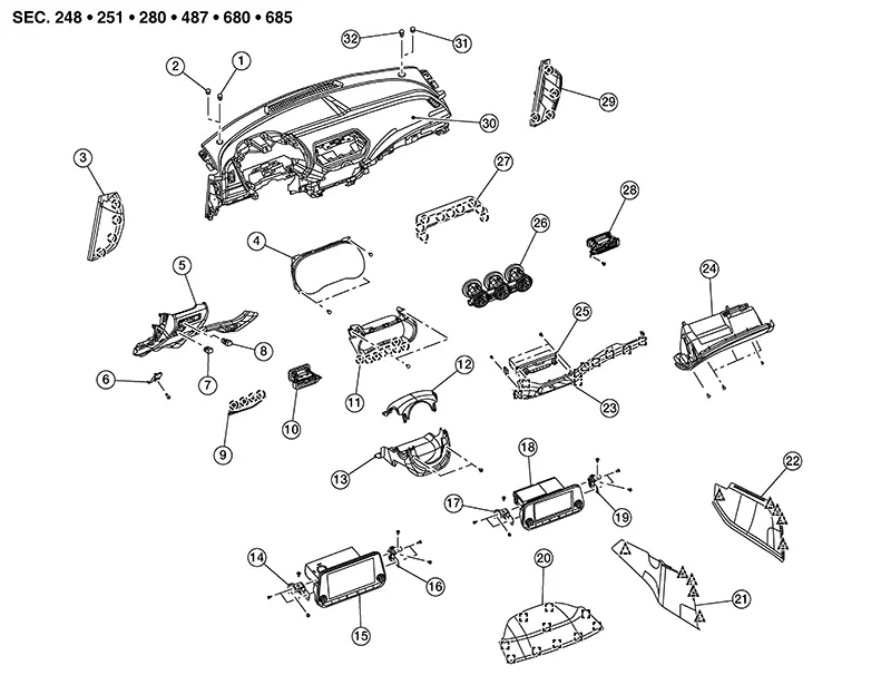
|
1. |
Optical sensor (if equipped) |
2. |
Mask |
3. |
Instrument side finisher (LH) |
|
4. |
Combination meter |
5. |
Instrument lower panel LH |
6. |
Fuel filler lid opener lever |
|
7. |
Trunk lid request switch |
8. |
ECO mode switch |
9. |
Fuse panel door |
|
10. |
Side ventilator grille (LH) |
11. |
Cluster lid A |
12. |
Steering column upper cover |
|
13. |
Steering column lower cover |
14. |
AV control unit bracket (LH) |
15. |
AV control unit (without base audio) |
|
16. |
AV control unit bracket (RH) |
17. |
AV control unit bracket (LH) |
18. |
AV control unit (with base audio) |
|
19. |
AV control unit bracket (RH) |
20. |
Cluster lid D |
21. |
Instrument lower cover (LH) |
|
22. |
Instrument lower cover (RH) |
23. |
Instrument finisher B |
24. |
Glove box assembly |
|
25. |
A/C switch assembly |
26. |
Center ventilator grille |
27. |
Cluster lid C |
|
28. |
Side ventilator grille (RH) |
29. |
Instrument side finisher (RH) |
30. |
Instrument panel assembly |
|
31. |
Sunload sensor (if equipped) |
32. |
Mask |
Removal and Installation
Removal and Installation
CAUTION:
-
Be careful not to scratch instrument panel and other parts.
-
Before servicing, turn ignition switch OFF, disconnect both battery terminals and wait at least three minutes.
REMOVAL
Disconnect the negative and positive battery terminals, then wait at least three minutes. Refer to Battery Disconnect.
Remove the front pillar finishers (LH/RH). Refer to Removal and Installation.
Remove instrument finisher B. Refer to Removal and Installation.
Remove cluster lid C. Refer to Removal and Installation.
Remove AV control unit. Refer to Removal and Installation (DISPLAY AUDIO WITH 7" COLOR DISPLAY), Removal and Installation (DISPLAY AUDIO WITHOUT BOSE WITH 8" COLOR DISPLAY), Removal and Installation (DISPLAY AUDIO WITH BOSE WITH 8" COLOR DISPLAY), Removal and Installation (INTELLIGENT AROUND VIEW MONITOR SYSTEM), Removal and Installation (REAR VIEW MONITOR WITH 7" COLOR DISPLAY), or Removal and Installation (REAR VIEW MONITOR WITH 8" COLOR DISPLAY).
Remove steering column covers. Refer to Removal and Installation.
Remove the steering wheel. Refer to Removal and Installation.
Remove the combination switch. Refer to Removal and Installation.
Remove the combination meter. Refer to Removal and Installation (Type A) or Removal and Installation (Type B).
Remove center ventilator grille. Refer to Removal and Installation.
Remove the side ventilator grille (RH). Refer to Removal and Installation.
Remove
bolts (A) from front passenger air bag module (1). 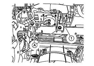
Remove the
instrument panel screws (A).
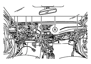
Disconnect the harness connector from the front passenger air bag module.
Disconnect all remaining harness connectors.
Remove the instrument panel assembly.
CAUTION:
Be careful not to scratch the instrument panel and other parts.
INSTALLATION
Installation is in the reverse order of removal.
-
If replacing the instrument panel, transfer all the necessary parts to the new instrument panel.
Steering Column Covers. Removal and Installation. Removal and Installation
Removal and Installation
REMOVAL
Using a
suitable tool, release pawls to detach cluster lid A (1) from
steering column upper cover (2). 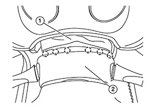
 :
Pawl
:
Pawl
Remove the
steering column upper cover and steering column lower cover screws
(A). 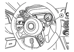 Note:
Note: 
RH shown; LH similar
Remove steering column upper cover and steering column lower cover.
INSTALLATION
Installation is in the reverse order of removal.
Instrument Finisher B. Removal and Installation. Removal and Installation
Removal and Installation
Remove cluster lid A. Refer to Removal and Installation.
Using a
suitable tool, release pawls and remove instrument side finishers
[1 (LH/RH)]. 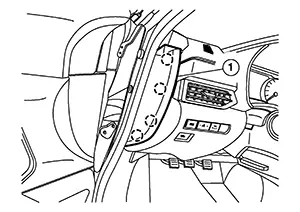 Note:
Note:
LH shown; RH similar
:
Pawl
Remove instrument lower panel LH. Refer to Removal and Installation.
Remove glove box assembly. Refer to Removal and Installation.
Remove center console assembly. Refer to Removal and Installation.
Using a
suitable tool, release clips. 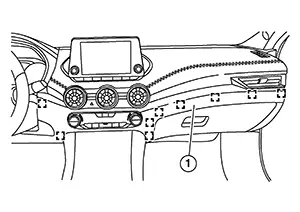
 : Metal clip
Disconnect aspirator hose (with automatic air conditioner) and remove instrument finisher B (1).
INSTALLATION
Installation is in the reverse order of removal.
Cluster Lid a. Removal and Installation. Removal and Installation
Removal and Installation
REMOVAL
Remove the instrument lower panel LH. Refer to Removal and Installation.
Remove cluster lid D. Refer to Removal and Installation.
Using a
suitable tool, release cluster lid A (1) clips and remove screws
(A).
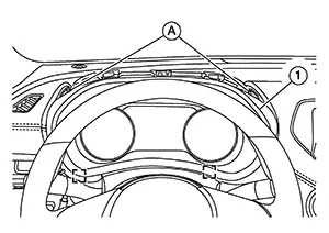
: Metal clip
Remove cluster lid A.
INSTALLATION
Installation is in the reverse order of removal.
Cluster Lid C. Removal and Installation. Removal and Installation
Removal and Installation
REMOVAL
Using a
suitable tool, release clips and pawls.
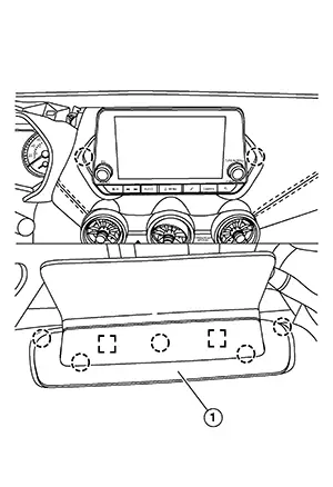
:
Pawl
: Metal clip
Remove cluster lid C (1).
INSTALLATION
Installation is in the reverse order of removal.
Cluster Lid D. Removal and Installation. Removal and Installation
Removal and Installation
Using a
suitable tool, release clips. 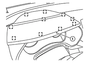
: Metal clip
Remove cluster lid D (1).
INSTALLATION
Installation is in the reverse order of removal.
Instrument Lower Panel Lh. Removal and Installation. Removal and Installation
Removal and Installation
REMOVAL
Using a
suitable tool, release pawls and remove the instrument side
finisher LH (1).
:
Pawl
Remove the fuel filler handle assembly. Refer to Exploded View.
Using a
suitable tool, release the instrument lower panel LH clips and
pawls.
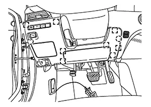
: Metal clip
:
Pawl
Disconnect harness connectors and remove the instrument lower panel LH.
INSTALLATION
Installation is in the reverse order of removal.
Glove Box Assembly. Removal and Installation. Removal and Installation
Removal and Installation
REMOVAL
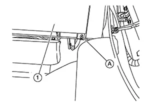
Remove the
glove box assembly upper screws (A).
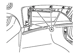
Remove the
glove box assembly (1) lower screw (A).
Using a
suitable tool, release clips and pawl and remove the glove box
assembly (1). 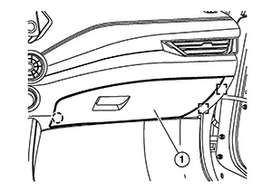
: Metal clip
:
Pawl
INSTALLATION
Installation is in the reverse order of removal.
Steering Member Assembly. Exploded View
Exploded View
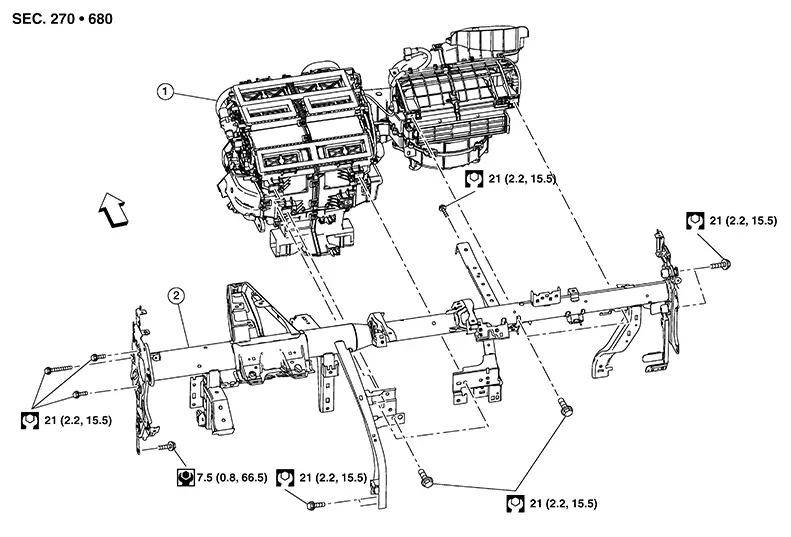
|
1. |
Heating and cooling unit assembly |
2. |
Steering member |
|
Front |

Removal and Installation
Removal and Installation
REMOVAL
Remove the front wiper drive assembly. Refer to Removal and Installation.
Remove
steering member bolts (A) in engine room. 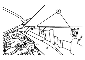
Remove the instrument panel assembly. Refer to Removal and Installation.
Remove left knee air bag module. Refer to Removal and Installation.
Remove right knee air bag module. Refer to Removal and Installation.
Remove bolt
(A) and separate lower joint (2) from steering column (1). 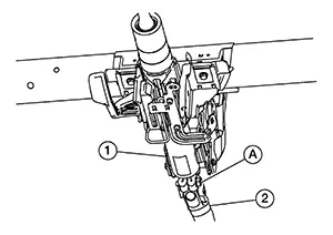
CAUTION:
Place a matching mark on both lower joint and steering column before separating.
Remove
bolts (A) and lower steering column to the floor. 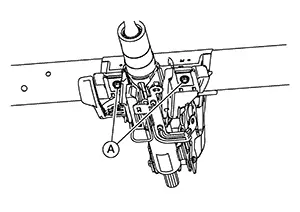
Remove heating and cooling unit assembly bolts. Refer to Exploded View.
Disconnect all necessary harness connectors.
Remove steering member bolts. Refer to Exploded View.
Remove steering member from Nissan Sentra vehicle.
CAUTION:
Two people are required for removal to prevent damage to steering member.
INSTALLATION
Installation is in the reverse order of removal.
Note:
If replacing steering member, transfer all of the necessary parts to the new steering member.
Center Console Assembly. Exploded View
Exploded View
CVT MODELS
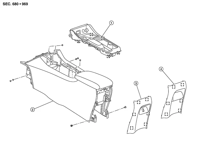
|
1. |
Shift selector finisher (CVT) |
2. |
Center console |
3. |
Center console rear finisher (with rear USB charge port) |
|
4. |
Center console rear finisher (without rear USB charge port) |
|
Pawl |
|
Metal clip |
M/T MODELS
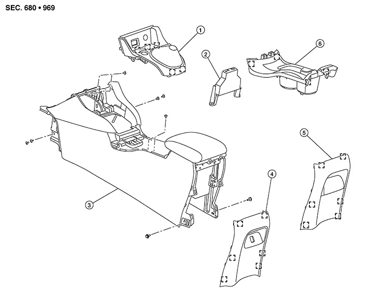
|
1. |
Shift selector finisher (with Manual transmission) |
2. |
Center console support bracket |
3. |
Center console |
|
4. |
Center console rear finisher (with USB charge port) |
5. |
Center console rear finisher (without USB charge port) |
6. |
Center console cup holder finisher |
|
|
Pawl |
|
Metal clip |
Removal and Installation
Removal and Installation
CVT MODELS
REMOVAL
Using a suitable tool, release clips
and remove the center console side finishers [1 (LH/RH)].
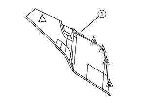 Note:
Note:
LH shown; RH similar
 : Clip
Remove shift selector finisher using the following steps:
-
Remove the CVT shift selector knob. Refer to Removal & Installation.
-
Using a suitable tool, release clips and pawls.
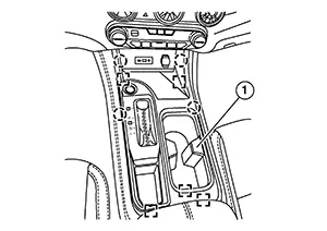 : Pawl: Metal clip
 - Disconnect harness connectors and remove the shift selector finisher (1).
Using a suitable tool, release clips
from center console rear finisher (1).
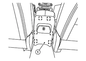
: Metal clip
Disconnect harness connector (if equipped) and remove the center console rear finisher.
Remove the screws (A).
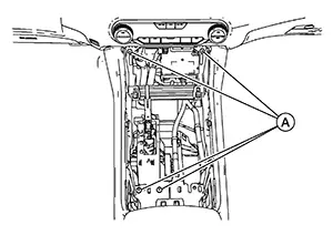
Remove screws [A (LH/RH)] from the
center console assembly (1).
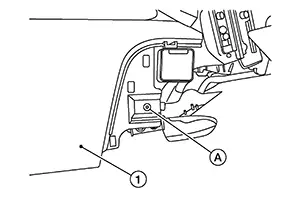 Note:
Note:
RH shown; LH similar
Remove screws (A) from the center
console assembly (1).
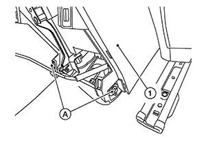
Disconnect harness connectors and remove center console assembly.
INSTALLATION
Installation is in the reverse order of removal.
M/T MODELS
REMOVAL
Using a suitable tool, release clips
and remove the center console side finishers [1 (LH/RH)].
Note:
LH shown; RH similar
: Clip
Remove shift selector finisher using the following steps:
-
Using suitable tool (A), remove shift knob finisher (1).
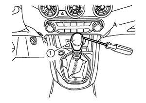
-
Remove shift knob (1) as shown.
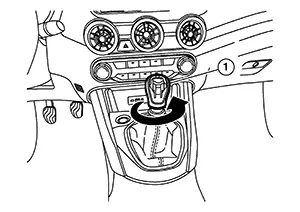
Using a suitable tool, release clips
of shift selector finisher (1).
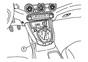
: Metal clip
Disconnect harness connector and remove shift selector finisher.
Using a suitable tool, release clips
and remove center console cup holder finisher (1).
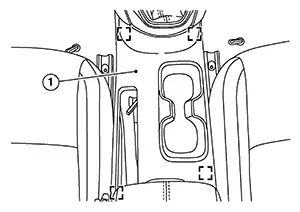
: Metal clip
Using a suitable tool, release clips
of center console rear finisher (1).
: Metal clip
Disconnect harness connector (if equipped) and remove center console rear finisher (1).
Remove screws (A) from center console
assembly (1).
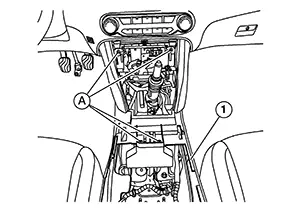
Remove screws [A (LH/RH)] from center
console assembly (1).
Note:
RH shown; LH similar
Remove screws (A) from center console
assembly (1).
Disconnect harness connectors and remove center console assembly.
INSTALLATION
Installation is in the reverse order of removal.
Other materials:
Types of tires
WARNING
When changing or replacing tires on your Nissan Sentra, always ensure
that all four tires are of the same type (Summer, All Season, or Snow) and the
same construction. A NISSAN dealer can assist you in selecting the correct tire
type, size, speed rating, and availability suitabl ...
Optical Sensor Circuit
Component Function Check
Component Function
Check
CHECK OPTICAL SENSOR SIGNAL
Ignition switch ON.
Turn lighting switch AUTO.
With the optical sen ...
Diagnosis System (air Bag)
Description
Description
CAUTION:
Never use electrical test equipment on any
circuit related to the SRS unless instructed in this Service
Manual. SRS wiring harnesses can be identified by yellow and/or
orange harnesses or harness connectors.
...