Nissan Sentra B18 (2020-2025) Service Manual: System
System Description
System Description
SYSTEM DIAGRAM
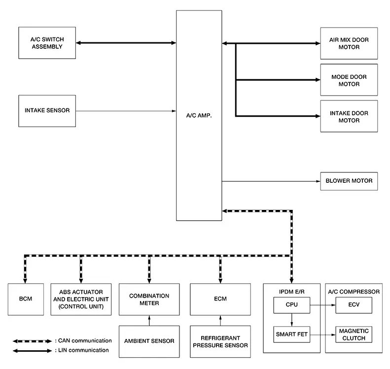
INPUT SIGNAL AND OUTPUT SIGNAL
|
Control unit |
Signal status |
|---|---|
|
ABS actuator and electric unit (control unit) |
Transmits the Nissan Sentra vehicle speed signal to A/C amp. via CAN communication. |
|
Combination meter |
Transmits the ambient temperature signal to A/C amp. via CAN communication. |
|
ECM |
|
|
IPDM E/R |
Smart EFT is integrated in IPDM E/R:
|
|
A/C switch assembly |
|
|
Air mix door motor |
|
|
Mode door motor |
|
|
Intake door motor |
DESCRIPTION
-
Manual air conditioning system is controlled by each function of A/C amp., ECM and IPDM E/R.
-
Each operation of air conditioning system can be controlled by the A/C switch assembly.
CONTROL BY A/C amp.
-
Air Inlet Control: refer to Air Inlet Control.
-
Door Control: Door Control.
-
Compressor Control: Compressor Control.
-
Cooling Fan Operation Request Control: Cooling Fan Control.
CORRECTION FOR INPUT VALUE
-
Ambient temperature correction
-
A/C amp. inputs the temperature detected by ambient temperature signal received from combination meter via CAN communication as the ambient temperature.
-
A/C amp. performs the correction of the temperature detected by ambient sensor for air conditioning control.
-
A/C amp. selects and uses the initial value of ambient temperature data depending on the engine coolant temperature when placing the ignition switch from OFF to ON. The detection temperature of the ambient sensor is used when engine coolant temperature is low [less than approximately 133┬░F (56┬░C)]. The memory data (before the ignition switch is OFF) when the engine is warmed up [approximately 133┬░F (56┬░C) or more].
-
The correction of the ambient temperature is not performed when the detection temperature of the ambient temperature is less than approximately ŌłÆ4┬░F (ŌłÆ20┬░C).
-
-
Intake temperature correction
-
A/C amp. inputs the temperature detected by intake sensor as the intake temperature (evaporator temperature).
-
A/C amp. performs the correction of the temperature detected by intake sensor for air conditioning control.
-
A/C amp. performs the correction so that the recognition intake temperature changes depending on the difference between the detected intake temperature and the recognition intake temperature. If the difference is large, the changing is early. The changing becomes slow as the difference becomes small.
-
CONTROL BY ECM
Compressor control: refer to Compressor Control.
CONTROL BY IPDM E/R
Compressor control: refer to Compressor Control.
Air Inlet Control
Air Inlet Control
DESCRIPTION
-
A/C amp. controls the intake door motor and switches the air inlets.
-
A/C amp. controls the air inlets so that they are set to fresh air intake, when A/C compressor is stopped by low temperature protection control.
-
When the following conditions are met, A/C amp. controls the air inlets to 20% recirculation. (However, this does not occur when high engine coolant temperature control is in effect.)
At this time, the intake switch indicator lamp turns OFF.
-
Fan control dial: 10th - 11th
-
Temperature control dial: Full hot
-
Air outlet mode: FOOT or DEF
-
HIGH ENGINE COOLANT TEMPERATURE CONTROL
When the following conditions is met, A/C amp. changes the air inlets to recirculation.
-
Air outlet: Other than D/F or DEF
-
A/C switch: ON
-
Ambient temperature: More than 77┬░F (25┬░C)
-
Nissan Sentra Vehicle speed: 30 km/h or more
-
Engine coolant temperature: 221┬░F (105┬░C) or more
Compressor Control
Compressor Control
DESCRIPTION
-
When the A/C compressor activation condition is satisfied while blower motor is activated, A/C amp. transmits A/C ON signal and blower fan ON signal to ECM via CAN communication line.
-
ECM judges the conditions of each sensor (Refrigerant pressure sensor signal, accelerator position signal, etc.), and transmits the A/C compressor request signal to IPDM E/R via CAN communication line.
-
By receiving the A/C compressor request signal from ECM, IPDM E/R turns the smart FET to ON, and activates the A/C compressor.
CONTROL BY A/C AMP.
Low Temperature Protection Control
When intake sensor detects that evaporator fin
temperature is  [23.0┬░F (ŌłÆ5.0┬░C) or less, A/C amp. requests
ECM to turn the A/C compressor OFF, and stops the A/C compressor.
[23.0┬░F (ŌłÆ5.0┬░C) or less, A/C amp. requests
ECM to turn the A/C compressor OFF, and stops the A/C compressor.
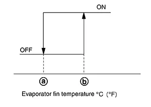
When the air temperature returns to  [33.8┬░F (1.0┬░C)] or more, the A/C
compressor
is activated.
[33.8┬░F (1.0┬░C)] or more, the A/C
compressor
is activated.
Refrigerant Discharge Amount Control
-
When setting temperature is full cold or air outlet is other than DEF, A/C amp. controls the refrigerant discharge amount by adjust the duty ratio of ECV according to required amount of cooling capacity.
-
When evaporator temperature is target temperature upper limit value or more, A/C amp. increases the discharge amount.
-
When evaporator temperature is less than target temperature upper limit value, A/C amp. reduces the discharge amount.

Target temperature upper limit value of evaporator can be changed using ŌĆ£TARGET EVAPORATOR TEMP UPPER LIMIT SETTINGŌĆØ in ŌĆ£Work supportŌĆØ mode of CONSULT. Refer to Diagnosis Description.
Compressor Oil Circulation Control
When the engine starts, A/C amp. activates the A/C compressor for a few seconds and circulates the A/C compressor oil once.
CONTROL BY ECM
Compressor Protection Control at Pressure Malfunction
The high-pressure side value that is detected by refrigerant pressure sensor is excessively low or high, ECM requests IPDM E/R to turn smart FET OFF and stop the A/C compressor.
Air Conditioning Cut Control
When the engine condition is high load, ECM transmit smart FET OFF request to IPDM E/R, and stops the A/C compressor.
Door Control
Door Control
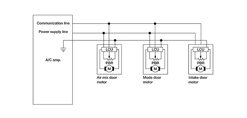
DOOR MOTOR CONTROL
-
LCU (Local Control Unit) is built into each door motor, and detects door position by PBR (Potentio Balance Resistor).
-
A/C amp. communicates with each LCU via communication line and receives each door position feedback signal from each LCU.
-
Each LCU controls each door to the appropriate position depending on the control signal from A/C amp.
-
Each LCU transmits the signal of door movement completion to A/C amp., when the door movement is completed.
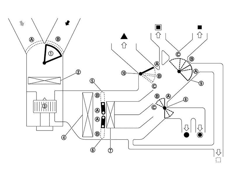
SWITCH AND THEIR CONTROL FUNCTION
|
|
Intake door |
|
Air conditioner filter |
|
Blower motor |
|
|
Evaporator |
|
Upper air mix door (driver side/passenger side) |
|
Lower air mix door (driver side/passenger side) |
|
|
Heater core |
|
Foot door |
|
Ventilator door |
|
|
Defroster door |
||||
|
|
Fresh air |
|
Recirculation air |
|
Discharge air |
|
|
Defroster |
|
Center ventilator |
|
Side ventilator |
|
|
Front foot |
|
Rear foot* |
|
Rear ventilator* |


*: With rear ventilator
|
Switch position |
Door position |
|||||||
|---|---|---|---|---|---|---|---|---|
|
Mode door |
Intake door |
Air mix door |
||||||
|
Ventilator door |
Foot door |
Defroster door |
||||||
|
MODE switch |
|
|
|
|
ŌĆö |
ŌĆö |
||
|
|
|
|
|
|||||
|
|
|
|
|
|||||
|
|
|
|
|
|||||
|
DEF switch |
|
|
|
|
|
|||
|
Intake switch |
REC |
|
|
ŌĆö |
ŌĆö |
ŌĆö |
|
|
|
FRE |
|
|
||||||
|
Temperature control dial |
Full cold |
ŌĆö |
|
|||||
|
Full cold ŌĆō Full hot |
|
|||||||
|
Full hot |
|
|||||||


AIR DISTRIBUTION
|
Discharge air flow |
|||||||
|---|---|---|---|---|---|---|---|
|
MODE/DEF setting position |
Air outlet/distribution |
||||||
|
Ventilator |
Foot |
Defroster |
|||||
|
Front |
Rear |
Front |
Rear |
||||
|
Center |
Side |
||||||
|
|
43% |
43% |
14% |
ŌĆö |
ŌĆö |
ŌĆö |
|
|
|
24% |
24% |
10% |
32% |
10% |
ŌĆö |
|
|
|
ŌĆö |
10% |
10% |
45% |
15% |
20% |
|
|
|
ŌĆö |
10% |
10% |
30% |
15% |
35% |
|
|
|
ŌĆö |
14% |
12% |
ŌĆö |
ŌĆö |
74% |
|
|
Discharge air flow |
|||||
|---|---|---|---|---|---|
|
MODE/DEF setting position |
Air outlet/distribution |
||||
|
Ventilator |
Foot |
Defroster |
|||
|
Center |
Side |
||||
|
|
51% |
49% |
ŌĆö |
ŌĆö |
|
|
|
30% |
30% |
40% |
ŌĆö |
|
|
|
ŌĆö |
10% |
65% |
25% |
|
|
|
ŌĆö |
10% |
50% |
40% |
|
|
|
ŌĆö |
16% |
ŌĆö |
84% |
|
Cooling Fan Control
Cooling Fan Control
DESCRIPTION
A/C amp. controls the cooling fan operation request according to the refrigerant pressure status and Nissan Sentra vehicle speed status.
Note:
For an overview of the cooling fan and information about control. Refer to System Description.
CONTROL OUTLINE
-
A/C amp. receives the refrigerant pressure sensor signal from ECM via CAN communication, Nissan Sentra vehicle speed signal from the ABS actuator and electric unit (control unit) via CAN communication and the intake sensor signal.
-
A/C amp. sets one of the optionally determined stages according to the received refrigerant pressure sensor signal, Nissan Sentra vehicle speed signal and intake sensor signal.
Note:
For the rules that prescribe the predetermined stages, refer to the following figures:
-
Nissan Sentra Vehicle speed stages
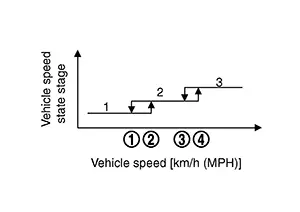
Nissan Sentra Vehicle speed [km/h (MPH)]
-
 : 12 (7.5)
 -
 : 20 (12)
 -
 : 72 (45)
 -
 : 80 (50)
-
-
Refrigerant pressure stages
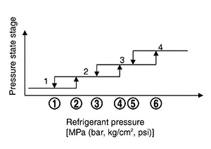
Refrigerant pressure [MPa (bar, kg/cm2, psi)]
-
: 1.28 (12.8, 13.1, 186)
-
: 1.28 (12.8, 13.1, 186)
-
: 1.28 (12.8, 13.1, 186)
-
: 1.28 (12.8, 13.1, 186)
-
 : 1.28 (12.8, 13.1, 186)
 -
 : 1.58 (15.8, 16.1, 229)
-
-
-
The requested cooling fan operation strength (0%, 40%, 100%) is determined according to the combination of these two stages, and the request signal is transmitted to ECM via CAN communication.
Note:
When evaporator temperature detected by intake sensor is high, request to the increase cooling fan operation strength.
Other materials:
Headlining
Exploded View
Exploded View
STANDARD ROOF
1.
Front room/map lamp assembly
bracket
2.
Headlining
...
Basic Inspection
Diagnosis and Repair Work Flow
Work Flow
Work Flow
OVERALL SEQUENCE
DETAILED FLOW
INTERVIEW FOR MALFUNCTION
It is also important to clarify the customer
concerns before starting the inspection. Interview the
customer about the concerns carefully and ...
C1711-7b Low Tire Pressure Fl
Dtc Description
DTC Description
Note:
The Signal Tech II Tool [ŌĆō (NI-50190)] can be used
to perform the following functions: Refer to the Signal Tech II User
Guide for additional information.
Activate and display TPMS sensor IDs
Display tire pressure rep ...