Nissan Sentra B18 (2020-2025) Service Manual: Removal and Installation
CAUTION:
-
Be careful not to scratch instrument panel and other parts.
-
Before servicing, turn ignition switch OFF, disconnect both battery terminals and wait at least three minutes.
REMOVAL
Disconnect the negative and positive battery terminals, then wait at least three minutes. Refer to Battery Disconnect.
Remove the front pillar finishers (LH/RH). Refer to Removal and Installation.
Remove instrument finisher B. Refer to Removal and Installation.
Remove cluster lid C. Refer to Removal and Installation.
Remove AV control unit. Refer to Removal and Installation (DISPLAY AUDIO WITH 7" COLOR DISPLAY), Removal and Installation (DISPLAY AUDIO WITHOUT BOSE WITH 8" COLOR DISPLAY), Removal and Installation (DISPLAY AUDIO WITH BOSE WITH 8" COLOR DISPLAY), Removal and Installation (INTELLIGENT AROUND VIEW MONITOR SYSTEM), Removal and Installation (REAR VIEW MONITOR WITH 7" COLOR DISPLAY), or Removal and Installation (REAR VIEW MONITOR WITH 8" COLOR DISPLAY).
Remove steering column covers. Refer to Removal and Installation.
Remove the steering wheel. Refer to Removal and Installation.
Remove the combination switch. Refer to Removal and Installation.
Remove the combination meter. Refer to Removal and Installation (Type A) or Removal and Installation (Type B).
Remove center ventilator grille. Refer to Removal and Installation.
Remove the side ventilator grille (RH). Refer to Removal and Installation.
Remove
bolts (A) from front passenger air bag module (1). 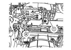
Remove the
instrument panel screws (A).
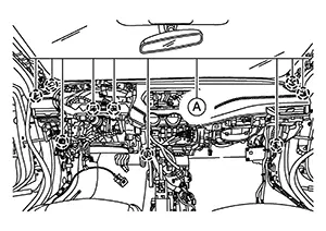
Disconnect the harness connector from the front passenger air bag module.
Disconnect all remaining harness connectors.
Remove the instrument panel assembly.
CAUTION:
Be careful not to scratch the instrument panel and other parts.
INSTALLATION
Installation is in the reverse order of removal.
-
If replacing the instrument panel, transfer all the necessary parts to the new instrument panel.
 Exploded View
Exploded View
1.
Optical sensor (if
equipped)
...

Other materials:
Specialservicetools
SpecialServiceTools
The actual shape
of the tools may differ from those illustrated here.
Tool number
(TechMate No.)
Tool name
Description
...
Rear Lh
Diagnosis Procedure
Diagnosis Procedure
CHECK REAR POWER WINDOW MOTOR LH
INPUT SIGNAL
Ignition switch OFF.
Disconnect rear power window motor LH
connector.
...
Main Line Between Abs and M&a Circuit
Diagnosis Procedure
Diagnosis Procedure
CHECK CONNECTOR
Turn the ignition switch OFF.
Disconnect the battery cable from the
negative terminal.
Check the following terminals and
...
