Nissan Sentra B18 (2020-2025) Service Manual: Rear Suspension :: Unit Removal and Installation. Rear Suspension Member
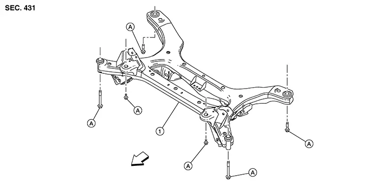
Rear Suspension Member. Exploded View
Exploded View
|
1. |
Rear suspension member |
A. |
Refer to installation Removal and installation. |
|
Front |
Removal and Installation
Removal and Installation
REMOVAL
For rear disc brake rotor, refer to Removal and Installation.
For rear brake assembly, refer to Removal and Installation.
Remove the wheel sensors and the wheel sensor harness. Refer to Exploded View.
Remove the exhaust main muffler assembly. Refer to Exploded View.
Remove the shock absorber lower bolts. Refer to Exploded View.
Remove EVAP canister. Refer to Removal and Installation.
Using suitable jack (A) support the rear suspension member.
Warning:
Place a suitable jack under the center of the rear suspension member.
CAUTION:
Do not damage the rear suspension member with the suitable jack.
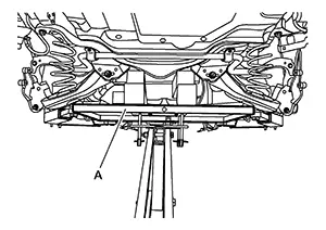
Slowly lower the suitable jack, then remove the upper coil spring seats and the coil springs.
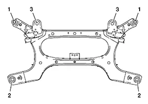
Remove the rear suspension member, the rear suspension arms, the radius rods, the front lower links, and the rear knuckles from the Nissan Sentra vehicle as a unit.
Remove coil spring lower rubber seat.
If necessary, remove rear knuckle (LH/RH). Refer to Removal and Installation (Disc brake) or Removal and Installation (Drum brake).
If necessary, remove the rear suspension arms. Refer to Removal and Installation.
If necessary, remove the front lower links. Refer to Removal and Installation.
INSTALLATION
Installation is in the reverse order of the removal.
-
Install the rear suspension member and tighten bolts in the sequence shown.
Bolts 1–3
: 172.5 N·m (18 kg-m, 127 ft-lb)
-
Perform final tightening of installation position between front suspension member and transverse links (rubber bushing) under unladen condition with tires on level ground.
-
Check wheel sensor harness for proper connection.
-
After installation, Check wheel alignment. Refer to Wheel Alignment (Unladen*1).
-
Adjust the neutral position of the steering angle sensor. Refer to Description.
CAUTION:
-
Do not reuse the rear suspension link nuts at the rear suspension member.
-
Do not reuse exhaust gaskets.
Other materials:
Power Supply and Ground Circuit
A/c Amp.
Diagnosis Procedure
Diagnosis Procedure
CHECK A/C AMP. GROUND CIRCUIT FOR
OPEN
Ignition switch OFF.
Disconnect A/C amp. connector.
...
Air cleaner
The viscous paper-type air cleaner filter element used in the Nissan Sentra is
designed for single use only and must not be cleaned or reused. The filter should
be replaced according to the maintenance intervals listed in the "Maintenance and
schedules" section of this manual to ...
System Settings Cannot Be Turned On/off
Diagnosis Procedure
Diagnosis Procedure
CHECK SYSTEM SETTING
Turn ignition switch ON.
Check that the each system settings is
selectable on the combination meter.
Is the inspection result norma ...