Nissan Sentra B18 (2020-2025) Service Manual: Rear Suspension :: Removal and Installation
Rear Knuckle. Exploded View
Exploded View
With Drum Brake
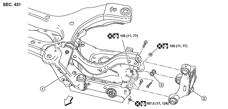
|
1. |
Rear suspension assembly |
2. |
Rear knuckle |
3. |
bushings |
|
|
Front |

With Disc Brake
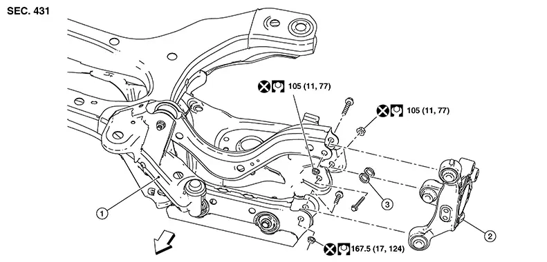
|
1. |
Rear suspension assembly |
2. |
Rear knuckle |
3. |
Bushing |
|
|
Front |
Removal and Installation - Disc Brake
Removal and Installation - Disc Brake
REMOVAL
Remove rear hub assembly. Refer to Removal and Installation.
Place a suitable jack under the outer end of the rear lower link to relieve the coil spring tension.
Warning:
Place a suitable jack under the outer end of the rear lower link.
CAUTION:
Do not damage the rear lower link with suitable jack.
Remove the front and rear lower link bolts from the rear knuckle.
Remove the upper arm bolt from the rear knuckle.
Remove the rear knuckle from the Nissan Sentra vehicle.
INSTALLATION
Installation is in the reverse order of removal.
-
Perform the final tightening of the parts under the unladen conditions with the tires on the ground.
Removal and Installation - Drum Brake
Removal and Installation - Drum Brake
REMOVAL
Remove rear hub assembly. Refer to Removal and Installation.
Place a suitable jack under the outer end of the rear lower link to relieve the coil spring tension.
Warning:
Place a suitable jack under the outer end of the rear lower link.
CAUTION:
Do not damage the rear lower link with suitable jack.
Remove the front and rear lower link bolts from the rear knuckle.
Remove the upper arm bolt from the rear knuckle.
Remove the rear knuckle from the Nissan Sentra vehicle.
INSTALLATION
Installation is in the reverse order of removal.
-
Perform the final tightening of the parts under the unladen conditions with the tires on the ground.
Rear Lower Link. Exploded View
Exploded View
With Drum Brake
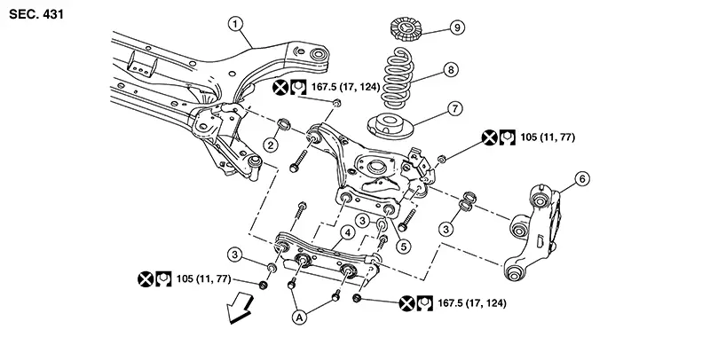
|
1. |
Rear suspension member |
2. |
Washer |
3. |
Washer |
|
4. |
Front lower link |
5. |
Rear lower link |
6. |
Rear knuckle |
|
7. |
Lower seat |
8. |
Spring |
9. |
Upper seat |
|
|
Front |
With Disc Brake
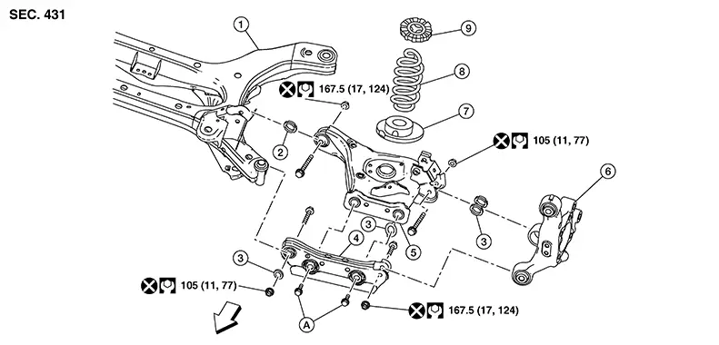
|
1. |
Rear suspension member |
2. |
Washer |
3. |
Washer |
|
4. |
Front lower link |
5. |
Rear lower link |
6. |
Rear knuckle |
|
7. |
Lower seat |
8. |
Spring |
9. |
Upper seat |
|
|
Front |
Removal and Installation
Removal and Installation
REMOVAL
Remove rear suspension member. Refer to Removal and Installation.
Remove the front and rear lower link nut and bolt from the rear suspension member using power tool.
Remove front and rear lower link nut and bolt from the rear knuckle using power tool.
Remove the front link and rear lower link as an assembly.
Remove lower rear suspension link bolts.
Separate front lower link and rear lower link.
INSTALLATION
Installation is in the reverse order of removal.
CAUTION:
Do not reuse rear lower nuts.
-
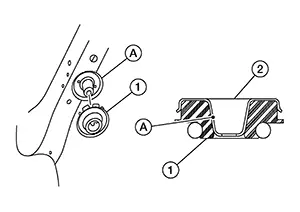
Make sure that the upper seat is attached as shown.
CAUTION:
-
Keep the upper seat (1) in place during coil spring installation. The protrusion (A) on the Nissan Sentra vehicle fits inside upper seat (2)
-
-
Match up the lower seat indentions and the rear lower link grooves.
-
When installing the coil spring, position the coil spring using marking.
CAUTION:
Position the coil spring with the 1 marking 1.75 turns from the top.
-
Install the coil spring by aligning the lower end of the coil spring (1) to the bump on the lower spring seat (2).
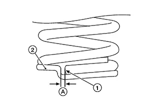
(A)
: Maximum gap 5 mm (0.20 in)
-
Perform the final tightening of the parts under unladen conditions with the tires on the ground.
-
Check the wheel alignment. Refer to Wheel Alignment (Unladen*1).
-
Adjust the neutral position of the steering angle sensor. Refer to Description.
Inspection
Inspection
INSPECTION AFTER REMOVAL
Check the upper rubber seat, the lower rubber seat, and the coil spring for deformation, cracks, and damage.
Replace the parts if necessary.
Radius Rod. Exploded View
Exploded View
With Drum Brake
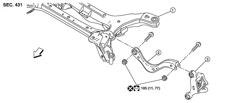
|
1. |
Rear suspension member |
2. |
Rear suspension arm |
3. |
Rear knuckle |
|
|
Front |
With Disc Brake
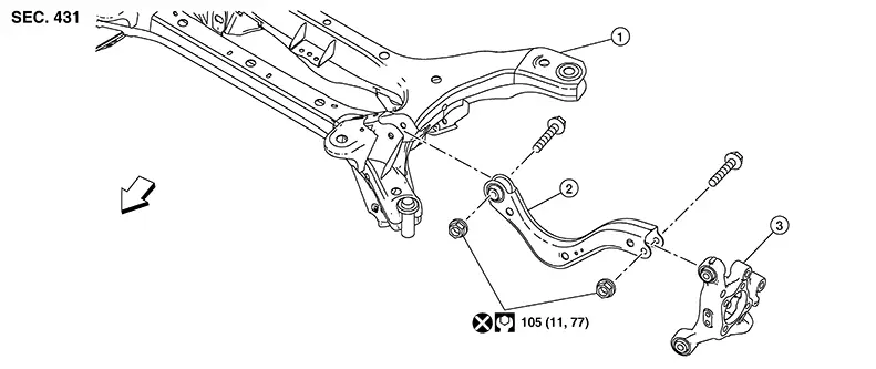
|
1. |
Rear suspension member |
2. |
Rear suspension arm |
3. |
Rear knuckle |
|
|
Front |
Removal and Installation
Removal and Installation
Removal
Remove rear suspension member. Refer to Removal and Installation.
Remove the suspension arm from the knuckle using power tool.
Remove the suspension arm from rear suspension member using power tool.
Installation
Installation is in the reverse order of removal.
-
Perform the final tightening of the suspension arm bolts and nuts at the knuckle, under unladen conditions with tires on level ground.
CAUTION:
Do not reuse the suspension arm nuts.
-
Check rear wheel alignment. Refer to Wheel Alignment (Unladen*1).
-
Adjust the neutral position on steering angle sensor. Refer to Description.
Front Lower Link. Exploded View
Exploded View
With Drum Brake
|
1. |
Rear suspension member |
2. |
Washer |
3. |
Washer |
|
4. |
Front lower link |
5. |
Rear lower link |
6. |
Rear knuckle |
|
7. |
Lower seat |
8. |
Spring |
9. |
Upper seat |
|
|
Front |
With Disc Brake
|
1. |
Rear suspension member |
2. |
Washer |
3. |
Washer |
|
4. |
Front lower link |
5. |
Rear lower link |
6. |
Rear knuckle |
|
7. |
Lower seat |
8. |
Spring |
9. |
Upper seat |
|
|
Front |
Removal and Installation
Removal and Installation
REMOVAL
Remove rear suspension member. Refer to Removal and Installation.
Remove the front and rear lower link nut and bolt from the rear suspension member using power tool.
Remove the front and rear lower link nut and bolt from the rear knuckle using power tool.
Remove the front lower link and rear lower link as an assembly.
Remove lower rear suspension link bolts.
Separate front lower link and rear lower link.
INSTALLATION
Installation is in the reverse order of removal.
CAUTION:
Do not reuse the front and rear lower link nuts.
-
Perform the final tightening of the parts under unladen conditions with the tires on the ground.
-
Check the wheel alignment. Refer to Wheel Alignment (Unladen*1).
-
Adjust the neutral position of the steering angle sensor. Refer to Description.
Rear Stabilizer. Exploded View
Exploded View
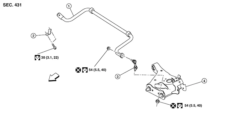
|
1. |
Stabilizer bar |
2. |
Stabilizer bar clamp |
3. |
Connecting rod |
|
4. |
Rear lower link |
|
Front |
Removal and Installation
Removal and Installation
REMOVAL
Remove rear suspension member. Refer to Removal and Installation.
Remove the lower connecting rod nuts.
Disconnect the connecting rods from the rear suspension links.
Remove the
stabilizer bar clamp bolts (A) using power tool.
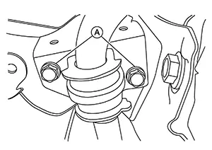
Remove the stabilizer bar clamps.
Remove the stabilizer bar.
Remove the connecting rod nuts from stabilizer bar and remove connecting rods.
INSTALLATION
Installation is in the reverse order of removal.
-
Tighten the connecting rod nut to the specified torque while holding the hexagonal part of the connecting rod stud.
Rear Shock Absorber. Exploded View
Exploded View
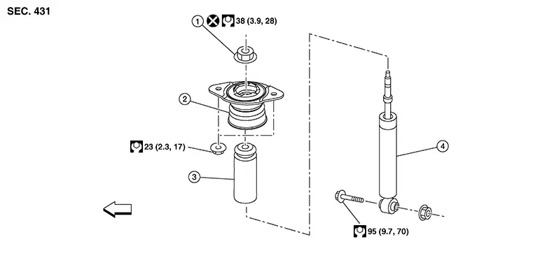
|
1. |
Piston rod lock nut |
2. |
Shock absorber insulator |
3. |
Bound bumper |
|
4. |
Rear shock absorber |
|
Front |
Removal and Installation
Removal and Installation
REMOVAL
Remove wheel and tire. Refer to Removal and Installation.
Place a suitable jack under the outer end of the rear lower link to relieve the coil spring tension.
Warning:
Place a suitable jack under the outer end of the rear lower link.
CAUTION:
Do not damage the rear lower link with suitable jack.
Remove the lower rear shock absorber bolt with suitable tool.
Gradually lower the suitable jack to separate the rear shock absorber from the rear lower link
Remove the
rear shock absorber upper nuts ( ).
).
Remove the rear shock absorber.
CAUTION:
Do not hit or damage the shock absorber piston rod. Hold the shock absorber body.
Inspect the components. Refer to Inspection.
INSTALLATION
Installation is in the reverse order of removal.
-
Perform the final tightening of the parts under the unladen conditions with the tires on the ground.
Inspection
Inspection
INSPECTION AFTER REMOVAL
Shock Absorber
Check the following items and replace the parts if necessary.
Check the shock absorber for oil leaks, deformation, cracks, and other damage.
Check the piston rod for damage, uneven wear, and distortion.
Bound Bumper, Bushing
Check for cracks and damage. Replace the parts if necessary.
Washer, Bound Bumper Cover, Distance Tube
-
Check for cracks and damage. Replace the parts if necessary.
Disposal
Disposal
Set the shock absorber horizontally with the piston rod fully extended.
Drill a 2
– 3 mm (0.08 – 0.12 in) hole at the position ( )
from the top as shown to release gas gradually.
)
from the top as shown to release gas gradually. 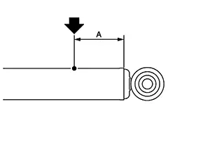
CAUTION:
-
Wear eye protection (safety glasses).
-
Wear gloves.
-
Be careful with metal chips or oil blown out by the compressed gas.

-
Drill vertically in this direction (
 )
directly to the outer tube avoiding brackets.
)
directly to the outer tube avoiding brackets. -
The gas is clear, colorless, odorless, and harmless.
|
(A) |
: 20 – 30 mm (0.79 – 1.18 in) |
Position the drilled hole downward and drain oil by moving the piston rod several times.
CAUTION:
Dispose of drained oil according to the law and local regulations.
Other materials:
B2f06-15 Back Door/trunk Opener Switch
Dtc Description
DTC Description
DTC DETECTION LOGIC
DTC No.
CONSULT screen items (Trouble
diagnosis content)
DTC detecting condition
...
Dtc/circuit Diagnosis
Eco Mode Switch
Component Function Check
Component Function Check
CHECK ECO MODE SWITCH OPERATION
Ignition switch ON.
Check ECO mode indicator turns ON/OFF
on combination meter when turn ECO mode switch
O ...
P0127 Iat Sensor
Dtc Description
DTC Description
DTC DETECTION LOGIC
DTC
CONSULT screen terms
(Trouble diagnosis
content)
DTC detection
condition
...