Nissan Sentra B18 (2020-2025) Service Manual: Diagnosis System (av Control Unit)
Description
Description
The AV control unit on board diagnosis performs the following functions listed in the table below:
|
Mode |
Description |
|
|---|---|---|
|
Self Diagnosis |
|
|
|
Confirmation/Adjustment |
Display Diagnosis |
The following check functions are available:
|
|
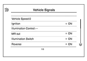
Nissan Sentra Vehicle Signals |
Diagnosis of signals can be performed for Nissan Sentra Vehicle Speed, Ignition, Illumination Control, MR out, Illumination Switch, Reverse, Parking Brake and ACC. |
|
|
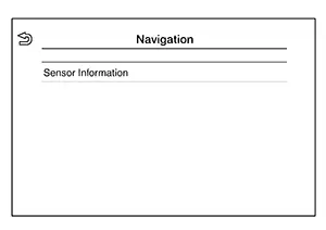
Navigation |
Displayed, but not used. |
|
|
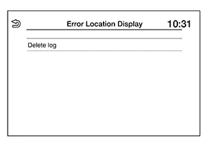
Error Location Display |
The system malfunction and the frequency when occurring in the past are displayed. When the malfunctioning item is selected, the time that the selected malfunction last occurred is displayed. |
|
|
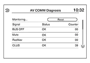
AV COMM Diagnosis |
The AV communication condition of each unit of audio system can be monitored. |
|
|
### Hands-Free Phone |
Maintenance can be performed. |
|
|
Camera |
The following functions are available:
|
|
|
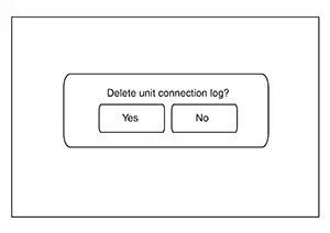
Delete Unit Connection Log |
Erase the connection history of unit. |
|
|
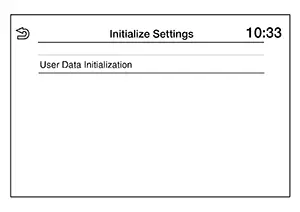
Initialize Settings |
User Data Initialization is available. |
|
|
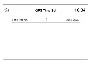
GPS Time Set |
Displayed, but not used. |
|
|
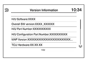
Version Information |
Version information of the Multi AV system is displayed. |
|
|
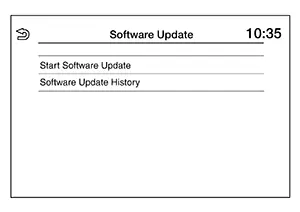
Software Update |
|
|
|
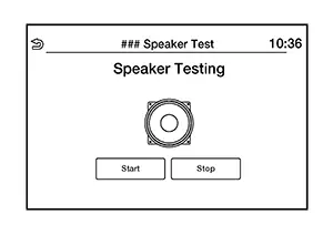
### Speaker Test |
Individual speakers can be checked at the 100Hz and 4KHz range. |
|
|
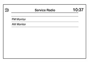
Radio Tuner |
FM Monitor and AM Monitor information can be observed. |
|
|
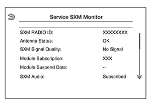
SXM |
SXM Monitor information can be observed. |
|
Perform CONSULT diagnosis if the AV control unit on board diagnosis does not start, or the screen does not display anything.
On Board Diagnosis Function
On Board Diagnosis Function
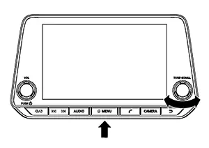
METHOD OF STARTING
AV Control Unit Self Diagnosis
-
Ignition switch ON.
-
Audio system OFF.
-
While pressing the MENU button, turn the TUNE-SCROLL dial clockwise or counterclockwise for 40 clicks or more. Shifting from current screen to previous screen is performed by pressing BACK button.
-
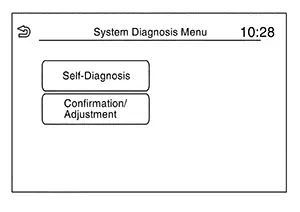
The trouble diagnosis initial screen is displayed, and “Self Diagnosis” and “Confirmation/Adjustment” can be selected.
SELF-DIAGNOSIS MODE
-
Start the self-diagnosis function and select “Self Diagnosis”.
-
Self-diagnosis subdivision screen is displayed, and the self-diagnosis mode starts.
-
The bar graph visible on the center of the self-diagnosis subdivision screen indicates progress of the trouble diagnosis.
-
-
Diagnosis results are displayed after the self-diagnosis is completed. The unit names and the connection lines are color-coded according to the diagnostic results.
Note:Diagnosis results
Unit
Connection line
Normal
Green
Green
Connection malfunction
Gray
Yellow
Unit malfunction Note
Red
Green

Control Unit (AV control unit) is displayed in red.
-
Replace AV control unit if “Self-Diagnosis did not run because of a control unit malfunction” is indicated. The symptom is AV control unit internal error. Refer to Removal and Installation.
-
If multiple errors occur at the same time for a single unit, the screen switch colors are determined according to the following order of priority: red > gray.
-
-
MCAN, Head Unit and VCAN are displayed:
-
Press the MCAN button and the system components connected via AV communication are displayed.
-
Press the Head Unit button and the components connected to the AV control unit are displayed.
-
Press the VCAN button and the system components connected via CAN communication are displayed. Refer to Trouble Diagnosis Flow Chart for CAN communication diagnosis.
-
Detection Range of Self-diagnosis Mode
-
The self-diagnosis mode allows the technician to diagnose the connection in the communication line between AV control unit and each unit and the internal operation of the AV control unit.
-
Because the start condition of diagnosis function is a switch operation, the on board diagnosis function cannot be started up if any malfunction is detected in the AV control unit switches.
SELF-DIAGNOSIS RESULTS
Only Unit Part Is Displayed In Red (MCAN)
|
Screen switch |
Description |
Possible malfunction location / Action to take |
|---|---|---|
|
Head Unit |
Malfunction is detected in AV control unit power supply and ground circuits. |
Check AV control unit power supply and ground circuits. Refer to Diagnosis Procedure. When no malfunction is detected in those circuits, replace AV control unit. Refer to Removal and Installation. |
|
TCU |
Malfunction is detected in TCU power supply and ground circuits. |
Check TCU power supply and ground circuits. Refer to Diagnosis Procedure. When no malfunction is detected in those circuits, replace TCU. Refer to Removal and Installation. |
|
Meter |
Malfunction is detected in combination meter power supply and ground circuits. |
Check combination meter power supply and ground circuits. Refer to Diagnosis Procedure. When no malfunction is detected in those circuits, replace combination meter. Refer to Removal and Installation. |
Only Unit Part Is Displayed In Red (Head Unit)
|
Screen switch |
Description |
Possible malfunction location / Action to take |
|---|---|---|
|
Head Unit |
Malfunction is detected in AV control unit power supply and ground circuits. |
Check AV control unit power supply and ground circuits. Refer to Diagnosis Procedure. When no malfunction is detected in those circuits, replace AV control unit. Refer to Removal and Installation. |
|
Amplifier |
Malfunction is detected in the internal amplifier of the AV control unit. |
Replace the AV control unit. Refer to Removal and Installation. |
|
Conn Modules |
|
Replace the AV control unit. Refer to Removal and Installation. |
|
Antenna |
|
Check window or satellite antenna. Refer to Antenna and Antenna Feeder (window antenna) or Diagnosis Procedure (satellite antenna). When no malfunction is detected, replace window or antenna. Refer to Removal and Installation (window antenna) or Removal and Installation (satellite antenna). |
|
Speaker |
Malfunction is detected in speaker signal circuit. |
Check speaker signal circuit. Refer to:
When no malfunction is detected in the circuit, replace speaker. Refer to:
|
|
Microphone |
Malfunction is detected in microphone signal circuit. |
Check microphone signal circuit. Refer to Diagnosis Procedure. When no malfunction is detected in the circuit, replace microphone. Refer to Removal and Installation. |
|
USB |
|
Check front auxiliary input jack signal circuits. Refer to Diagnosis Procedure. When no malfunction is detected in the circuits, replace front auxiliary input jack. Refer to Removal and Installation. |
|
FAN |
Malfunction is detected in the internal fan of the AV control unit. |
Replace the AV control unit. Refer to Removal and Installation. |
A Connecting Cable Between Units Is Displayed In Yellow (MCAN)
|
Area with yellow connection lines |
Description |
Possible malfunction location / Action to take |
|---|---|---|
|
Head unit ⇔ TCU |
TCU AV communication connection malfunction detected. |
AV communication circuits between AV control unit and TCU. Refer to Diagnosis Procedure. |
|
Head unit ⇔ Meter |
Combination meter AV communication connection malfunction detected. |
AV communication circuits between AV control unit and combination meter. Refer to Diagnosis Procedure. |
A Connecting Cable Between Units Is Displayed In Yellow (Head Unit)
|
Area with yellow connection lines |
Description |
Possible malfunction location / Action to take |
|---|---|---|
|
Head Unit ⇔ Amplifier |
Internal amplifier malfunction detected. |
Replace the AV control unit. Refer to Removal and Installation. |
|
Head Unit ⇔ Conn Modules |
|
Replace the AV control unit. Refer to Removal and Installation. |
|
Head Unit ⇔ Antenna |
|
Window or satellite antenna disconnected. Refer to Antenna and Antenna Feeder (window antenna) or Diagnosis Procedure (satellite antenna). |
|
Head Unit ⇔ Speaker |
Speaker connection malfunction detected. |
Speaker disconnected. Refer to:
|
|
Head Unit ⇔ Microphone |
Microphone connection malfunction detected. |
Microphone disconnected. Refer to Diagnosis Procedure. |
|
Head unit ⇔ USB |
|
Refer to Diagnosis Procedure. |
|
Head Unit ⇔ FAN |
Internal fan malfunction detected. |
Replace the AV control unit. Refer to Removal and Installation. |
CONFIRMATION/ADJUSTMENT MODE
-
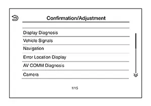
Start the diagnosis function and select “Confirmation/Adjustment”. The confirmation/adjustment mode indicates where each item can be checked or adjusted.
-
Select each switch on the “Confirmation/Adjustment Mode” screen to display the relevant trouble diagnosis screen. Touch the “Back” to return to the initial Confirmation/Adjustment Mode screen.
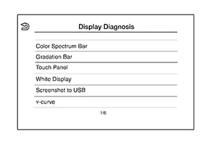
Display Diagnosis
Confirmation of the AV control unit screen operation.
Nissan Sentra Vehicle Signals
A comparison check can be made of each actual vehicle signal and the signals recognized by the system.
Navigation
Displayed, but not used.
Error Location Display
Results of the error occurrence are represented by the time the error occurred.
AV COMM Diagnosis
AV COMM Monitor
-
Displays the communication status between AV control unit (master unit) and each unit.
-
The error counter displays “OK” if any malfunction was not detected in the past and displays “0” if a malfunction is detected. It increases by 1 if the condition is normal at the next ignition switch ON cycle. The upper limit of the counter is 39.
-
The error counter is erased if “Reset” is pressed.
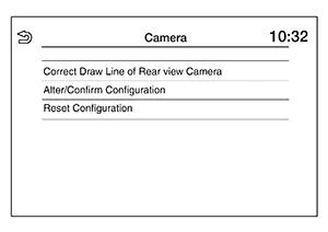
Camera
|
Item |
Description |
|---|---|
|
Correct Draw Line of Rear view Camera |
The guiding lines in the rear view monitor can be adjusted. |
|
Alter/Confirm Configuration |
Displays the current configuration data. |
|
Reset Configuration |
Initializes the camera system configuration. |
Delete Unit Connection Log
Deletes error records from the AV control unit memory.
Initialize Settings
Initializes the AV control unit memory.
GPS Time Set
Displayed, but not used.
Version Information
Version information of the components of the AV control unit system are displayed.
Software Update
Version of the AV control unit software can be update.
### Speaker Test
Two test tones, 100Hz and 4KHz, can be generated to each speaker.
Radio Tuner
Displays FM and AM monitor information.
SXM
Displays SXM monitor information.
Consult Function
CONSULT Function
CONSULT FUNCTIONS
CONSULT performs the following functions via communication with the AV Control unit:
|
Diagnosis Mode |
CGW Status |
Description |
||
|---|---|---|---|---|
|
Restricted Mode |
Diag Test Mode |
Open Mode |
||
|
ECU Identification |
Display |
Display |
Display |
The AV control unit part number is displayed. |
|
Self Diagnostic Result |
Display |
Display |
Display |
The AV control unit self diagnostic results are displayed. |
|
CGW Information |
Display |
Display |
Display |
|
|
Data Monitor |
Display |
Display |
Display |
The AV control unit input/output data is displayed in real time. |
|
Work Support |
Non-display |
Non-display |
Display |
Save or write VIN information. |
|
Configuration |
Display |
Display |
Display |
|
|
CAN Diag Support Monitor* |
Display |
Display |
Display |
Note:
The mode is indicated, but not monitored. |
|
Network-DTC* |
Display |
Display |
Display |
Display network DTC which AV control unit memorizes when performing "Diagnosis (All System)". |
*: Displays when performing "Diagnosis (All System)".
ECU IDENTIFICATION
The part number of AV control unit is displayed.
SELF DIAGNOSTIC RESULT
Refer to DTC Index.
CGW INFORMATION
Displays the diagnosis mode which a user can perform in Diag Test mode/Open Mode by switching the CGW status from Restricted mode to Diag Test Mode/Open Mode.
For the method of switching CAN Gateway status, refer to CONSULT Function.
DATA MONITOR
Note:
The following table includes information (items) inapplicable to this Nissan Sentra vehicle. For information (items) applicable to this vehicle, refer to CONSULT display items.
|
Monitor Item [Unit] |
Description |
|---|---|
|
Sunload sensor [On/Off] |
Indicates sunload sensor signal received from A/C auto amp. on CAN communication line. |
|
Parking brake [On/Off] |
Indicates condition of parking brake signal for the AV control unit. |
|
IGN SIG [On/Off] |
Indicates condition of ignition signal. |
|
Auto ACC [On/Off] |
Indicates condition of auto ACC signal. |
|
ACC [On/Off] |
Indicates condition of ACC signal. |
|
Aux IN 1 [Con/No con] |
Indicates connection condition of Aux in jack. |
|
Aux IN 2 [Con/No con] |
Indicates connection condition of USB. |
|
TCU mute signal [On/Off] |
Indicates condition of mute signal received from TCU. |
|
REV SIG [On/Off] |
Indicates condition of reverse signal received from transmission range switch. |
|
ILLUM SIG [On/Off] |
Indicates condition of illumination signal for the AV control unit. |
|
Illumination Control[On/Off] |
Indicates condition of illumination control signal for the AV control unit. |
WORK SUPPORT
|
Test item |
Description |
|---|---|
|
SAVE VIN DATA |
Allows the reading of VIN data written in AV control unit to store the specification in CONSULT. |
|
WRITE VIN (SAVED DATA) |
Allows the writing of the VIN data stored in CONSULT into the AV control unit. |
|
WRITE VIN (MANUAL INPUT) |
Allows the writing of the VIN data into the AV control unit by hand. |
CONFIGURATION
Configuration has three functions as follows.
|
Function |
Description |
|
|---|---|---|
|
Read/Write Configuration |
Before Replace ECU |
Allows the reading of Nissan Sentra vehicle specification written in AV control unit to store the specification in CONSULT. |
|
After Replace ECU |
Allows the writing of the Nissan Sentra vehicle information stored in CONSULT into the AV control unit. |
|
|
Manual Configuration |
Allows the writing of the Nissan Sentra vehicle specification into the AV control unit by hand. |
|
Other materials:
Rear Bumper
Exploded View
Exploded View
EXCEPT FOR SR
1.
Rear bumper side bracket (LH)
2.
Rear bumper reinforcement support
(L ...
B0012-55 Active Vent
Dtc Description
DTC Description
DTC DETECTION LOGIC
DTC No.
CONSULT screen items
(Trouble diagnosis
content)
DTC Detection Condition
...
Tire pressure
Tire Pressure Monitoring System (TPMS)
WARNING
Radio waves emitted by the Tire Pressure Monitoring System (TPMS) may adversely
affect certain types of electronic medical equipment.
Individuals who use a pacemaker or other implanted medical devices should
contact the medical equipment manufact ...