Nissan Sentra B18 (2020-2025) Service Manual: Ecu Diagnosis Information. Av Control Unit
Av Control Unit
Values on the Diagnosis Tool
Values on the Diagnosis Tool
Note:
The following table includes information (items) inapplicable to this Nissan Sentra vehicle. For information (items) applicable to this vehicle, refer to CONSULT display items.
|
Monitor Item |
Condition |
Value/Status |
|---|---|---|
|
Sunload sensor |
— |
Off |
|
— |
On |
|
|
Parking brake |
Parking brake not applied. |
Off |
|
Parking brake applied. |
On |
|
|
IGN SIG |
Ignition switch OFF. |
Off |
|
Ignition switch ON. |
On |
|
|
Auto ACC |
Auto accessory mode OFF. |
Off |
|
Auto accessory mode ON. |
On |
|
|
ACC |
Accessory mode OFF. |
Off |
|
Accessory mode ON. |
On |
|
|
Aux IN 1 |
Accessory not connected to aux in jack. |
Off |
|
Accessory connected to aux in jack. |
On |
|
|
Aux IN 2 |
Accessory not connected to USB. |
Off |
|
Accessory connected to USB. |
On |
|
|
TCU mute signal |
TCU not sending mute signal. |
Off |
|
TCU sending mute signal. |
On |
|
|
REV SIG |
Selector lever in any position other than R. |
Off |
|
Selector lever in R position. |
On |
|
|
ILLUM SIG |
Illumination signal not received. |
Off |
|
Illumination signal received. |
On |
|
|
Illumination Control |
Illumination control signal not received. |
Off |
|
Illumination control signal received. |
On |
Reference Value
Reference Value
TERMINAL LAYOUT
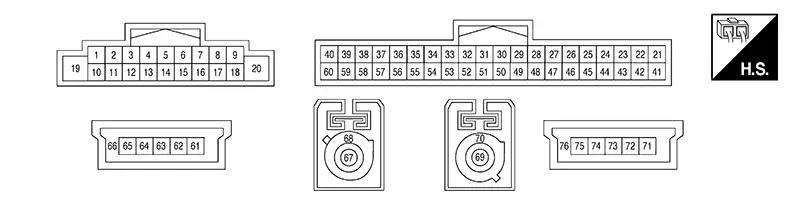
PHYSICAL VALUES
|
Terminal (Wire color) |
Description |
Condition |
Reference value (Approx.) |
|||
|---|---|---|---|---|---|---|
|
+ |
– |
Signal name |
Input/Output |
Ignition switch |
Operation |
|
|
2 (BR) |
3 (SB) |
Sound signal front door speaker and front tweeter LH |
Output |
ON |
Sound output |
 |
|
4 (LG) |
5 (P) |
Sound signal rear speaker LH |
Output |
ON |
Sound output |
|
|
11 (B) |
12 (W) |
Sound signal front door speaker and front tweeter RH |
Output |
ON |
Sound output |
|
|
13 (G) |
14 (R) |
Sound signal rear speaker RH |
Output |
ON |
Sound output |
|
|
19 (P) |
Ground |
Battery power supply |
Input |
OFF |
— |
Battery voltage |
|
20 (B) |
Ground |
Ground |
— |
ON |
— |
0 V |
|
21 (V)1 (B)2 |
42 (Shield)1 (LA/B)2 |
Microphone signal |
Input |
ON |
While speaking into microphone. |
|
|
22 (LG) |
Ground |
MIC VCC |
Output |
ON |
— |
5 V |
|
27 (L) |
Ground |
AUX jack audio signal RH |
Input |
ON |
Received audio signal (AUX input) |
|
|
28 (Y) |
Ground |
AUX ground |
— |
ON |
— |
0 V |
|
292 (W) |
492 (B) |
Telematics microphone signal |
Input |
ON |
While speaking into microphone. |
|
|
302 (Shield) |
— |
Telematics microphone signal shield |
— |
— |
— |
— |
|
32 (W) |
Ground |
Camera ground |
— |
ON |
— |
0 V |
|
33 (R) |
Ground |
Camera power supply |
Output |
ON |
Camera image displayed |
6.0 V |
|
Except for above |
0 V |
|||||
|
38 (LA/SB) |
— |
AV communication high |
Input/Output |
— |
— |
— |
|
39 (LA/SB) |
— |
AV communication high |
Input/Output |
— |
— |
— |
|
40 (LA/SB) |
— |
CAN-High |
Input/Output |
— |
— |
— |
|
47 (G) |
Ground |
AUX jack audio signal LH |
Input |
ON |
Received audio signal (AUX input) |
|
|
48 (Shield) |
— |
AUX signal shield |
— |
— |
— |
— |
|
50 (Y) |
— |
HF/VR mode change |
— |
— |
— |
— |
|
52 (B) |
53 (Shield) |
Camera image signal |
Input |
ON |
Camera image displayed |
 |
|
58 (LA/LG) |
— |
AV communication low |
Input/Output |
— |
— |
— |
|
59 (LA/LG) |
— |
AV communication low |
Input/Output |
— |
— |
— |
|
60 (LA/V) |
— |
CAN-Low |
Input/Output |
— |
— |
— |
|
61 (Y) |
— |
USB ground |
— |
— |
— |
— |
|
63 (L) |
— |
USB D+ signal |
— |
— |
— |
— |
|
64 (G) |
— |
USB D− signal |
— |
— |
— |
— |
|
65 (R) |
— |
V BUS signal |
— |
— |
— |
— |
|
66 (Shield) |
— |
USB shield |
— |
— |
— |
— |
|
67 (B) |
Ground |
AM/FM antenna signal |
Input |
ON |
AV control unit ON, FM-AM selected. |
5.0 V |
|
68 (Shield) |
— |
AM/FM antenna shield |
— |
— |
— |
— |
|
69 (B) |
Ground |
Satellite antenna signal |
Input |
ON |
AV control unit ON, XM selected. |
5.0 V |
|
70 (Shield) |
— |
Satellite antenna shield |
— |
— |
— |
— |
|
712 (B) |
— |
USB ground |
— |
— |
— |
— |
|
732 (G) |
— |
USB D+ signal |
— |
— |
— |
— |
|
742 (W) |
— |
USB D− signal |
— |
— |
— |
— |
|
752 (R) |
— |
V BUS signal |
— |
— |
— |
— |
|
762 (Shield) |
— |
USB shield |
— |
— |
— |
— |
1: Without Telematics System
2: With Telematics System
Fail Safe
Fail Safe
|
DTC |
AV control unit operation in fail-safe mode |
|---|---|
|
B1305-04 |
AV control unit internal error |
|
B130B-11 |
Rear door speaker RH inoperative |
|
B130B-12 |
|
|
B130B-13 |
|
|
B130B-1C |
|
|
B130D-11 |
|
|
B130D-12 |
|
|
B130D-13 |
Front door speaker RH inoperative |
|
B130D-1C |
|
|
B130F-11 |
|
|
B130F-12 |
|
|
B130F-13 |
Front door speaker LH inoperative |
|
B130F-1C |
|
|
B1311-11 |
Rear door speaker LH inoperative |
|
B1311-12 |
|
|
B1311-13 |
|
|
B1311-1C |
|
|
B1315-11 |
No AM/FM radio reception |
|
B1315-13 |
|
|
B1317-11 |
No satellite radio reception |
|
B1317-13 |
|
|
B1321-13 |
Front tweeter RH inoperative |
|
B1322-13 |
Front tweeter LH inoperative |
|
B1328-11 |
Microphone is inoperative |
|
B1328-12 |
|
|
B1328-13 |
|
|
B132A-01 |
USB is inoperative |
|
B132A-13 |
|
|
B132A-49 |
|
|
B132C-01 |
Telematics system inoperative |
|
B132C-13 |
|
|
B132C-49 |
|
|
B1339-8F |
Rear view camera is inoperative |
|
B1341-16 |
Battery protection shuts AV control unit down 60 seconds after low voltage condition |
|
B1341-17 |
|
|
B1341-49 |
AV control unit internal failure |
|
B1341-55 |
AV control unit configuration error |
|
B1341-98 |
AV control unit shuts down after 5 seconds |
|
B1342-62 |
Audio and visual system features are unavailable |
|
B1343-41 |
AV control unit ROM error |
|
B1344-41 |
AV control unit EEPROM error |
|
B1345-49 |
AV control unit Gyro error |
|
B1347-49 |
Bluetooth® is inoperative |
|
B1351-4B |
AV control unit shuts down and cannot restart for more than 5 minutes |
|
B1356-49 |
AV control unit DSP error |
|
B135E-49 |
AV control unit fan error |
|
B1360-02 |
Steering switch is inoperative |
|
B1375-11 |
Rear view camera is inoperative |
|
B1375-12 |
|
|
B1375-13 |
|
|
B1380-49 |
Wi-fi function is inoperative |
|
B1383-01 |
Predictive course line is not displayed |
|
B13CF-73 |
AV control unit buttons error |
|
B13D9-8F |
USB devices connected to front auxiliary input jacks are inoperative |
|
B13E5-8F |
Telematics system inoperative |
|
U0079-00 |
CAN communication does not function |
|
U1000-01 |
Function of CAN communication signals received by AV control unit are inoperative |
|
U1300-01 |
AV communication is inoperative |
Dtc Inspection Priority Chart
DTC Inspection Priority Chart
If multiple DTCs are detected simultaneously, check them one by one depending on the following DTC inspection priority chart:
|
Priority |
Detected items (DTC) |
|---|---|
|
1 |
|
|
2 |
|
|
3 |
|
Dtc Index
DTC Index
|
CONSULT Display |
Reference Page |
|---|---|
|
B1305-04: Control unit internal error |
DTC Description |
|
B130B-11: Rear RH speaker |
DTC Description |
|
B130B-12: Rear RH speaker |
|
|
B130B-13: Rear RH speaker |
|
|
B130B-1C: Rear RH speaker |
|
|
B130D-11: Front RH speaker |
DTC Description |
|
B130D-12: Front RH speaker |
|
|
B130D-13: Front RH speaker |
|
|
B130D-1C: Front RH speaker |
|
|
B130F-11: Front LH speaker |
DTC Description |
|
B130F-12: Front LH speaker |
|
|
B130F-13: Front LH speaker |
|
|
B130F-1C: Front LH speaker |
|
|
B1311-11: Rear LH speaker |
DTC Description |
|
B1311-12: Rear LH speaker |
|
|
B1311-13: Rear LH speaker |
|
|
B1311-1C: Rear LH speaker |
|
|
B1315-11: AM/FM 1 antenna |
DTC Description |
|
B1315-13: AM/FM 1 antenna |
|
|
B1317-11: XM antenna connection |
DTC Description |
|
B1317-13: XM antenna connection |
|
|
B1321-13: Front right tweeter |
DTC Description |
|
B1322-13: Front left tweeter |
DTC Description |
|
B1328-11: External microphone 1 |
DTC Description |
|
B1328-12: External microphone 1 |
|
|
B1328-13: External microphone 1 |
|
|
B132A-01: External USB |
DTC Description |
|
B132A-13: External USB |
|
|
B132A-49: External USB |
|
|
B132C-01: TCU Connection |
DTC Description |
|
B132C-13: TCU Connection |
|
|
B132C-49: TCU Connection |
|
|
B1339-8F: Rear camera connection |
DTC Description |
|
B1341-16: Head unit |
DTC Description |
|
B1341-17: Head unit |
|
|
B1341-49: Head unit |
|
|
B1341-55: Head unit |
|
|
B1341-98: Head unit |
|
|
B1342-62: Locked system |
DTC Description |
|
B1343-41: ECU Rom |
DTC Description |
|
B1344-41: ECU EEPROM |
DTC Description |
|
B1345-49: ECU Gyro |
DTC Description |
|
B1347-49: ECU Bluetooth module |
DTC Description |
|
B1351-4B: ECU Amplifier |
DTC Description |
|
B1356-49: ECU DSP |
DTC Description |
|
B135E-49: ECU Fan |
DTC Description |
|
B1360-02: Combination meter |
DTC Description |
|
B1375-11: Rear camera Power supply |
DTC Description |
|
B1375-12: Rear camera Power supply |
|
|
B1375-13: Rear camera Power supply |
|
|
B1380-49: ECU Wifi module |
DTC Description |
|
B1383-01: Incomp steering angle sensor adjust |
DTC Description |
|
B13CF-73: Buttons |
DTC Description |
|
B13D9-8F: USB communication error |
DTC Description |
|
B13E5-8F: TCU connection |
DTC Description |
|
U0079-00: Control module communication Bus G Off |
DTC Description |
|
U1000-01: CAN COMM CIRCUIT |
DTC Description |
|
U1300-01: AV communication circuit |
DTC Description |
Other materials:
INSTALLATION. Sonar Buzzer. Removal and Installation
CAUTION:
Verify that the connector direction is within the
specification shown when assembling the bumper fascia.
(A)
: Horizontal position
(a)
...
Rear Window Glass
Exploded View
Exploded View
1.
Spacer
2.
Rear window glass
3.
Adhesive ...
Stop Lamp
Component Inspection
Component Inspection
CHECK STOP LAMP 1
Ignition switch OFF.
Disconnect rear combination lamp (body side) connector
and high-mounted stop lamp connector. ...