Nissan Sentra B18 (2020-2025) Service Manual: Rear Brake Caliper Assembly
Exploded View
Exploded View
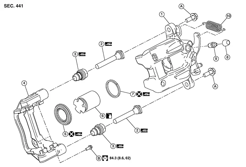
|
1. |
Brake caliper body |
2. |
Slide pin |
3. |
Slide pin boot |
|
4. |
Torque member |
5. |
Piston boot |
6. |
Piston |
|
7. |
Piston seal |
8. |
Bleeder cap |
9. |
Bleeder valve |
|
10. |
Return spring |
A. |
Slide pin bolt |
B. |
Torque member bolt |
|
|
Brake fluid |

Removal and Installation
Removal and Installation
Warning:
Clean dust on the brake caliper and the brake pads using a vacuum dust collector to minimize the hazards of airborne particles or other material.
CAUTION:
-
Do not depress the brake pedal while removing the brake pads because the piston may pop out.
-
Do not spill or splash brake fluid on painted surfaces. Brake fluid may seriously damage paint. Wipe it off immediately and wash with water if it gets on a painted surface.
-
Do not bend, twist, or pull the brake hoses and piping.
-
Do not reuse drained brake fluid.

When removing components such as hoses, tubes/lines, etc., cap or plug openings to prevent fluid from spilling.
REMOVAL
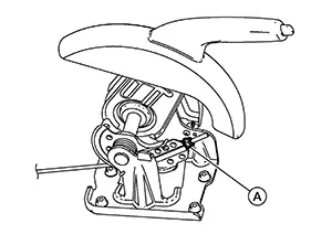
Loosen the parking brake adjuster nut using the following steps: For Nissan Sentra vehicles equipped with hand lever with rear disc brakes, perform the following procedure.
-
Remove the cup holder finisher. Refer to Exploded View.
-
Pull the parking brake lever.
-
Insert a suitable tool onto the adjusting nut (A) and rotate the adjusting nut to fully loosen the cable, then release the parking brake lever.
CAUTION:
Do not reuse the adjusting nut if the nut is removed.
Note:
It is not necessary to remove the adjusting nut.
-
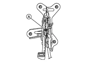
Depress the parking brake pedal.
-
Insert a suitable tool onto the adjusting nut (A) and rotate the adjusting nut to fully loosen the cable, then release the parking brake pedal.
CAUTION:
Do not reuse the adjusting nut if the nut is removed.
Note:
It is not necessary to remove the adjusting nut.
Observe the brake fluid level in the master cylinder reservoir tank. Partially drain brake fluid if necessary. Refer to Draining.
Remove the rear wheel and tire using power tool. Refer to Removal and Installation.
Remove the bolts from the parking brake bracket on the rear knuckle. Refer to Exploded View (HAND LEVER WITH REAR DISC BRAKES) or to Exploded View (FOOT PEDAL WITH REAR DISC BRAKES).
Remove the return spring from the rear brake caliper. Refer to Exploded View.
Move the parking brake lever in the rearward direction and pull the rear parking brake cable in the forward direction. Separate the rear parking brake cable from the lever.
Secure the disc brake rotor using wheel nuts.
Remove the union bolt, the copper sealing washers, and disconnect the brake hose from the brake caliper. Discard the copper sealing washers. Refer to Exploded View.
CAUTION:
Do not reuse copper sealing washers.
Remove the slide pin bolts.
Remove the brake caliper from the torque member.
CAUTION:
Do not drop the brake pads, the shims, or the brake caliper.
Remove the brake pads, shims, pad springs, and pad retainers from the torque member. Refer to Exploded View.
CAUTION:
-
Do not damage the pad retainers or the piston boot.
-
Do not drop the brake pads, shims, or pad retainers.
-
Note the position of components during removal to aid with installation.
Remove the torque member bolts and the torque member.
INSTALLATION
Install the torque member and the torque member bolts. Tighten the torque member bolts to the specified torque. Refer to Exploded View.
Install the brake pads, shims, pad springs, and pad retainers to the torque member. Refer to Exploded View.
CAUTION:
Do not drop the brake pads, shims, or pad retainers.
Install the brake caliper to the torque member.
Install the slide pin bolts.
Assemble
the union bolt (A) and the copper sealing washers (1) to the brake
hose and install it as an assembly to the brake caliper. Align the
brake hose L-pin by aligning it with the brake caliper hole, and
tighten the union bolt to the specified torque. Refer to Exploded View. 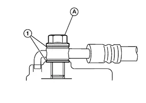
CAUTION:
Do not reuse copper sealing washers.
Install the rear parking brake cable to the lever. Refer to Exploded View (HAND LEVER WITH REAR DISC BRAKES) or to Exploded View (FOOT PEDAL WITH REAR DISC BRAKES).
Install the return spring to the rear brake caliper.
Install the parking brake bracket with the bolts to the rear knuckle.
Refill with new brake fluid and bleed air from the brake system. Refer to Bleeding Brake System.
CAUTION:
-
Do not reuse drained brake fluid.
-
Do not spill or splash brake fluid on the disc brake rotor.
Depress the brake pedal several times and perform the inspection after installation.
Install the rear wheel and tire. Refer to Removal and Installation.
INSPECTION AFTER INSTALLATION
Check the drag of the rear disc brake. If any drag is found, perform the following procedure: Remove the brake pads. Refer to Removal and Installation. Using a suitable tool, turn the piston into the brake caliper body.
CAUTION:
Do not damage the piston boot.
Install the brake pads. Depress the brake pedal several times. Check the drag of the rear disc brake again. If any drag is found, disassemble the brake caliper body. Refer to Disassembly and Assembly.Burnish contact surfaces after replacing the brake caliper or if a soft pedal occurs at very low mileage. Refer to Periodic Maintenance Operation.
Disassembly and Assembly
Disassembly and Assembly
Warning:
Clean dust on the brake caliper using a vacuum dust collector to minimize the hazards of airborne particles or other material.
CAUTION:
-
Do not reuse drained brake fluid.
-
Do not damage the piston seal.
DISASSEMBLY
Remove the brake caliper from the Nissan Sentra vehicle. Refer to Removal and Installation.
Remove the slide pins and the slide pin boots from the torque member. Refer to Exploded View.
Using a suitable tool, turn the piston to move the piston out and remove the piston boot from the brake caliper body.
CAUTION:
-
Do not damage cylinder inner wall.
-
Do not reuse the piston boot.
Remove the bleeder valve and cap.
Perform the inspection after disassembly.
INSPECTION AFTER DISASSEMBLY
Brake Caliper Body
Check the brake caliper body for rust, wear, cracks, and damage. Replace the brake caliper if any abnormal condition is detected.
CAUTION:
Clean the brake caliper using new brake fluid. Do not use mineral oils such as gasoline or kerosene.
Torque Member
Check the torque member for rust, wear, cracks, and damage. Replace the brake caliper if any abnormal condition is detected.
Piston
Check the piston surface for rust, wear, cracks, and damage. Replace the brake caliper if any abnormal condition is detected.
CAUTION:
The piston sliding surface is plated. Do not polish with sandpaper.
Slide Pins and Bolts
Check the slide pins and bolts for rust, wear, cracks, and damage. Replace the parts if any abnormal condition is detected.
ASSEMBLY
Install the bleeder valve and cap. Refer to Exploded View.
Apply
grease to the new piston boot (1). Apply brake fluid to the piston
(2). Cover the piston end with the new piston boot. Install the
cylinder side lip on the piston boot securely into the groove on
the brake caliper body. 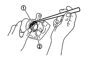
CAUTION:
Do not reuse the piston boot.
Turn the
piston (1) into the brake caliper body by hand and push the piston
boot (2) piston-side lip into the piston groove. 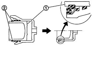
CAUTION:
Press the piston evenly and vary the pressing point to prevent the cylinder inner wall from being rubbed.
Apply
grease to the matching surfaces (A) of the slide pins (1) and the
slide pin boots (2). 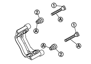
Install the slide pins and slide pin boots to the torque member.
Install the brake caliper to the Nissan Sentra vehicle. Refer to Removal and Installation.
Other materials:
Horn. Precaution. Precautions. Precaution for Supplemental Restraint System (srs) "air Bag" and "seat Belt Pre-Tensioner"
Precautions. Precaution for Supplemental Restraint System (srs) "air Bag" and "seat Belt Pre-Tensioner"
Precaution for Supplemental Restraint System (srs) "air Bag" and "seat Belt Pre-Tensioner"
Precaution for Supplemental Restraint System (SRS) "AIR BAG" an ...
Door Lock and Unlock Switch
Driver Side
Component Function Check
Component Function
Check
CHECK FUNCTION
CONSULT
Ignition switch ON.
Select ″CDL LOCK SW″, ″CDL UNLOCK SW″ in ″Data
...
Outside Key Antenna
Outside Key Antenna (rear Door Lh)
Removal and Installation
Removal and Installation
REMOVAL
Remove rear
door finisher (LH). Refer to Removal and Installation.
Disconnect
the harness connector from the outside key antenna (rear door
LH).
Release
clips and remove out ...