Nissan Sentra B18 (2020-2025) Service Manual: Preparation. Preparation
Preparation
Special Service Tools
Special Service Tools
The actual shape of the tools may differ from those illustrated here.
|
Tool number (TechMate No.) Tool name |
Description |
|
|---|---|---|
|
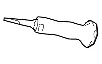
KV10111100 (NI-37228) Seal cutter |
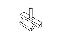 |
Removing oil pan (upper and lower) etc. |
|
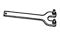
KV10112100 (BT-8653-A) Angle wrench |
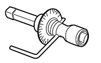 |
Tightening bolts for main bearing cap, cylinder head, etc. |
|
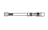
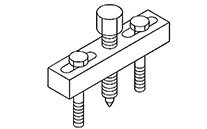
KV101197S0 (NI-50364) Injector seal drift set
|
 |
Installing fuel injector seal |
|
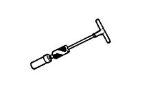
 —  (NI-48891) Spark plug wrench |
 |
Removing and installing spark plug |
|
 —  (NI-52553) Cam cover seal installer |
 |
Installing camshaft sprocket (INT) oil seal |
|
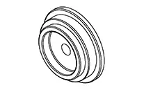
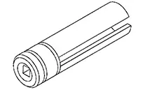
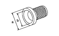
KV38107900 (NI-52469-1) Differential side oil seal protector |
 |
Installing drive shaft A: 32 mm (1.26 in) dia B: Minimum 23 mm (0.91 in) |
|
(NI-52982) Lock nut chisel (Cape chisel) |
 |
Removing wheel hub lock nut |
Commercial Service Tools
Commercial Service Tools
|
(TechMate No.) Tool name |
Description |
|
|---|---|---|
|
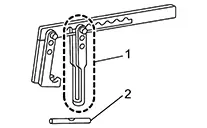
( — ) Pulley holder |
 |
Crankshaft pulley removing and installing |
|
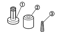
( — ) Valve spring compressor Attachment Adapter |
 |
Disassembling and assembling valve mechanism Part (1) is a component of KV10116200, but Part (2) is not so. |
|
( — ) Valve oil seal puller |
 |
Removing valve oil seal |
|
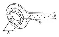
( — ) Valve oil seal drift |
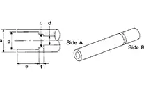 |
Installing valve oil seal Use side A. a: 20 (0.79) dia. d: 8 (0.31) dia. b: 13 (0.51) dia. e: 10.7 (0.421) c: 10.3 (0.406) dia. f: 5 (0.20) Unit: mm (in) |
|
( — ) Piston ring compressor |
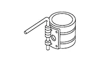 |
Installing piston assembly into cylinder bore
|
|
( — ) Pulley puller |
 |
Removing crankshaft pulley |
|
( — ) Heated oxygen sensor wrench |
 |
Loosening or tightening heated oxygen sensor 1 For 22 mm (0.87 in) width hexagon nut |
|
( — ) Valve seat cutter set |
 |
Finishing valve seat dimensions |
|
( — ) Piston ring expander |
 |
Removing and installing piston ring |
|
( — ) Valve guide drift |
 |
Removing and installing valve guide |
|
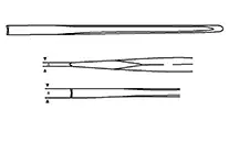
( — ) Valve guide reamer |
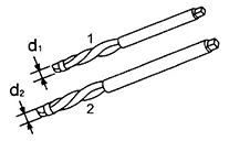 |
1: Reaming valve guide inner hole 2: Reaming hole for oversize valve guide d1: 6.0 mm (0.236 in) dia. d2: 10.2 mm (0.402 in) dia. |
|
( — ) Manual lift table caddy |
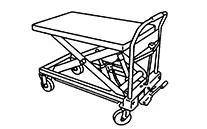 |
Removing and installing engine |
|
( — ) Tube presser |
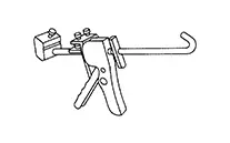 |
Pressing the tube of liquid gasket |
|
( — ) Engine stand |
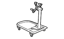 |
Engine overhaul |
|
( — ) Drift |
 |
Installing front oil seal a: φ57.0 mm (2.244 in). b: φ45.0 mm (1.772 in). |
|
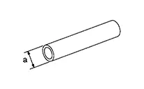
( — ) Drift |
|
Installing rear oil seal a: φ115.0 mm (4.528 in). b: φ90.0 mm (3.543 in). |
|
( — ) Stick |
 |
Installing rear oil seal a: φ18.0 mm (0.709 in). |
|
( — ) Compression gauge set |
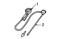 |
Compression pressure 1: Compression gauge 2: Adapter |
|
( — ) Lock nut crimp punch (Cold chisel) |
 |
Installing wheel hub lock nut a: 5 mm (0.20 in) b: 7 mm (0.28 in) |
Other materials:
Trip computer
1. Vehicle speed
The vehicle speed screen shows the current speed of the Nissan Sentra as well
as the average vehicle speed calculated since the last reset.
Average vehicle speed:
Press the OK button on the steering wheel to open the drive computer Reset menu,
then follow the on-screen in ...
P0746-00 Pressure Control Solenoid a
Dtc Description
DTC Description
DTC DETECTION LOGIC
DTC
CONSULT screen terms
(Trouble diagnosis
content)
DTC detection
conditi ...
Cooling Fan
Exploded View
Exploded View
1.
Reservoir tank
cap
2.
Reservoir tank
3.
...