Nissan Sentra B18 (2020-2025) Service Manual: Basic Inspection
Camshaft Valve Clearance
Inspection and Adjustment
Inspection and Adjustment
INSPECTION
Perform inspection as follows after removal, installation or replacement of camshaft or valve-related parts, or if there is unusual engine conditions regarding valve clearance.
Remove rocker cover. Refer to Removal and Installation.
Measure the valve clearance with the following procedure: Set No. 1 cylinder at TDC of its compression stroke.
-
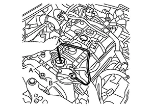
Rotate crankshaft pulley (1) clockwise and align TDC mark [no paint (B)] to timing indicator (A) on front cover.
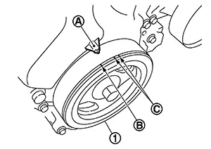
(C)
: White paint mark (Not use for service)
-
At the same time, check that both intake and exhaust cam noses of No. 1 cylinder face inside (
 )
as shown in the figure.
)
as shown in the figure.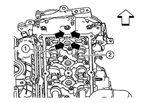
(1)
: Camshaft (INT)
(2)
: Camshaft (EXT)

: Engine front
-
If they do not face inside, rotate crankshaft pulley once more (360 degrees) and align as shown in the figure.
|
Valve clearance |
: Refer to Camshaft. |
-
By referring to the figure, measure the valve clearances at locations marked “×” as shown in the table below [locations indicated with black arrow (
)] with a suitable
tool.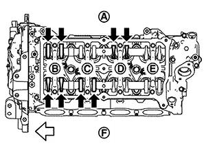
(A)
: Exhaust side
(B)
: No. 1 cylinder
(C)
: No. 2 cylinder
(D)
: No. 3 cylinder
(E)
: No. 4 cylinder
(F)
: Intake side
: Engine front
Measuring position
No. 1 CYL.
No. 2 CYL.
No. 3 CYL.
No. 4 CYL.
No. 1 cylinder at compression TDC
EXH
Ă—
Ă—
INT
Ă—
Ă—
-
Rotate crankshaft pulley (1) one revolution (360 degrees) and align TDC mark [no paint (B)] to timing indicator (A) on front cover.
(C)
: White paint mark (Not use for service)
-
By referring to the figure, measure the valve clearance at locations marked “×” as shown in the table below [locations indicated with black arrow (
)] with a suitable
tool.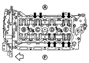
(A)
: Exhaust side
(B)
: No. 1 cylinder
(C)
: No. 2 cylinder
(D)
: No. 3 cylinder
(E)
: No. 4 cylinder
(F)
: Intake side
: Engine front
Measuring position
No. 1 CYL.
No. 2 CYL.
No. 3 CYL.
No. 4 CYL.
No. 4 cylinder at compression TDC
EXH
Ă—
Ă—
INT
Ă—
Ă—
If out of standard, perform adjustment. Refer to “ADJUSTMENT”.
ADJUSTMENT
-
Perform adjustment depending on selected head thickness of valve lifter.
Remove camshaft. Refer to Removal and Installation.
Remove valve lifters at the locations that are out of the standard.
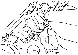
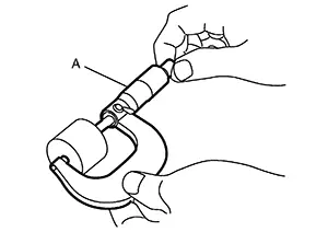
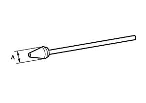
Measure the
center thickness of the removed valve lifters with a suitable tool
(A).
Use the equation below to calculate valve lifter thickness for replacement.
|
Valve lifter thickness calculation: |
t = t1 + (C1 – C2) |
||||
|
t |
= Valve lifter thickness to be replaced |
||||
|
t1 |
= Removed valve lifter thickness |
||||
|
C1 |
= Measured valve clearance |
||||
|
C2 |
= Standard valve clearance: |
||||
|
Intake |
: 0.28 mm (0.011 in) |
||||
|
Exhaust |
: 0.30 mm (0.012 in) |
||||
-
Thickness of new valve lifter (B) can be identified by stamp mark (A) on the reverse side (inside the cylinder).
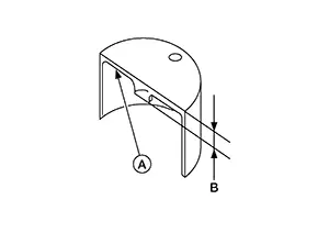
-
Stamp marks “302, 02FS, 02fs, 02Fb, 02fB" indicate 3.02 mm (0.1189 in) in thickness for intake valve lifters and "302, 02JS, 02js, 02JB, 02jb" indicate 3.02 mm (0.1189 in) in thickness for exhaust valve lifters.

Available thickness of valve lifter: 26 sizes range 3.00 to 3.50 mm (0.1181 to 0.1378 in) in steps of 0.02 mm (0.0008 in) (when manufactured at factory). Refer to Camshaft.
Install the selected valve lifter.
Install camshaft. Refer to Removal and Installation.
Install timing chain and related parts. Refer to Removal and Installation.
Manually rotate crankshaft pulley a few rotations.
Check that the valve clearances is within the standard. Refer to “INSPECTION”.
Installation of the remaining parts is in the reverse order of removal.
Warm up the engine, and check for unusual noise and vibration.
Compression Pressure
Inspection
Inspection
Warm up engine to full operating temperature. Stop engine.
Release the fuel pressure. Refer to Work Procedure.
Remove the fuel pump fuse from IPDM E/R to avoid fuel injection during measurement.
Remove ignition coil and spark plug from each cylinder. Refer to Removal and Installation.
Connect engine tachometer (not required when using CONSULT).
Install
suitable tool (A) with suitable tool (B) onto spark plug
hole.
-
Use compression tester whose end (rubber portion) is smaller than 20 mm (0.79 in) in diameter (A). Otherwise, it may be caught by cylinder head during removal.
With accelerator pedal fully depressed, crank engine. When the gauge pointer stabilizes, read the compression pressure and the engine rpm. Perform these steps to check each cylinder.
|
Compression pressure |
: Refer to General Specification. |
CAUTION:
Always use a fully charged battery to obtain the specified engine speed.
-
If the engine speed is out of the specified range, check the battery. Check the engine speed again with a fully charged battery.
-
If some cylinder has low compression pressure, pour small amount of engine oil into the spark plug hole of the cylinder to recheck it for compression.
-
If the added engine oil improves the compression, piston rings may be worn out or damaged. Check piston rings and replace if necessary.
-
If the compression pressure remains at low level despite the addition of engine oil, valves may be malfunctioning. Check valves for damage. Replace valve or valve seat accordingly.
-
-
If two adjacent cylinders have respectively low compression pressure and their compression remains low even after the addition of engine oil, cylinder head gaskets are leaking. In such a case, replace cylinder head gaskets.
-
If compression pressure is below minimum value, check valve clearances, and parts associated with combustion chamber (valve, valve seat, piston, piston ring, cylinder bore, cylinder head, cylinder head gasket). After the checking, measure compression pressure again.
After inspection is completed, installation is in the reverse order of removal.
Start the engine, and check that the engine runs smoothly.
Perform trouble diagnosis. If DTC appears, erase it. Refer to Work Procedure.
Other materials:
Brake Booster
Exploded View
Exploded View
1.
Brake booster
2.
Vacuum sensor
3.
Space ...
Reference Value
Reference Value
TERMINAL LAYOUT
PHYSICAL VALUES
Terminal No.
(Wire color)
Description
Condition
Value
...
Diagnosis System (bcm)
Common Item
Consult Function (bcm - Common Item)
CONSULT Function (BCM - COMMON ITEM)
BCM
Refer to CONSULT Function (BCM - COMMON ITEM).
Int Lamp
Consult Function (bcm - Int Lamp)
CON ...