Nissan Sentra B18 (2020-2025) Service Manual: Brake Booster
Exploded View
Exploded View
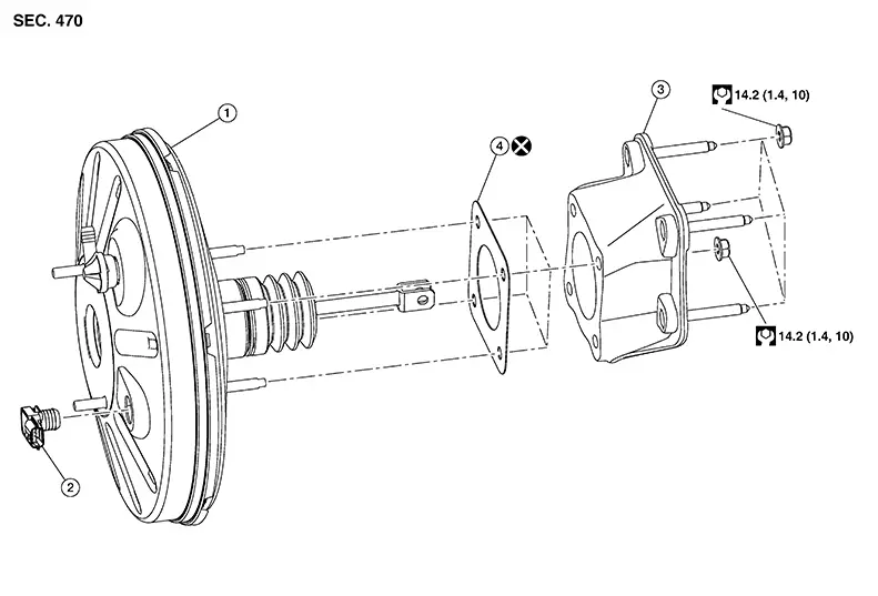
|
1. |
Brake booster |
2. |
Vacuum sensor |
3. |
Spacer |
|
4. |
Gasket |
Removal and Installation
Removal and installation
CAUTION:
-
Do not spill or splash brake fluid on painted surfaces. Brake fluid may seriously damage paint. Wipe it off immediately and wash with water if it gets on a painted surface.
-
Do not reuse drained brake fluid.

When removing components such as hoses, tubes/lines, etc., cap or plug openings to prevent fluid from spilling.
REMOVAL
Disconnect the negative terminal from the battery. Refer to Battery Disconnect.
Remove the master cylinder assembly. Refer to Removal and Installation.
CAUTION:
Do not deform or bend the brake tubes.
Disconnect the harness connector from the vacuum sensor.
Separate the vacuum hose from the vacuum booster. Refer to Exploded View and to Exploded View.
CAUTION:
Support the brake booster to avoid dropping or contacting other parts.
Remove brake pedal nuts and remove the brake pedal. Refer to Removal and Installation.
Place the accelerator pedal aside.
Remove the torque rod. Refer to Removal and Installation.
Remove engine mounting insulator (LH). Refer to Removal and Installation.
Remove the stud from the engine mounting bracket (LH). Refer to Exploded View.
Using the suitable jack, lower the engine and transmission.
Separate the brake pipes from the clamps on the cowl and place brake pipes aside. Refer to Exploded View.
Remove the brake booster, gasket and spacer as an assembly.
If necessary, remove the nuts and the remove the spacer.
If necessary, remove the gasket.
If necessary, remove the vacuum sensor.
INSPECTION AFTER REMOVAL
-
Measure the input rod (A) length (B).
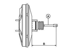
Input rod (A) length (B)
: Refer to Brake Booster.
-
If the input rod length is not the standard, replace the brake booster.
Note:
The input rod length is not adjustable.
-
Make sure the check valve (3) angle (A) and the vacuum sensor (2) angle (B) match the specifications for brake booster (1).
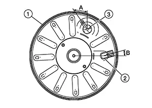
Check valve (3) angle (A)
: Refer to Brake Booster.
Vacuum sensor (2) angle (B)
: Refer to Brake Booster.
INSTALLATION
Installation is in the reverse order of removal.
-
Apply multi-purpose grease to the clevis pin. Refer to Exploded View.
-
Bleed air from the hydraulic brake system. Refer to Bleeding Brake System.
-
Inspect the brake pedal. Refer to Inspection.
-
Inspect the brake booster. Refer to Inspection.
-
Perform "ADDITIONAL SERVICE WHEN REMOVING BATTERY NEGATIVE TERMINAL". Refer to Special Repair Requirement.
CAUTION:
-
Do not reuse the gasket.
-
Be careful not to damage brake booster stud bolt threads. If brake booster is tilted during installation, the dash panel may damage the threads.
-
Make sure the brake hoses and tubes are not twisted or bent.
-
Replace the brake pedal if it has been dropped or sustained an impact.
Other materials:
B1341 Head Unit
Dtc Description
DTC Description
DTC DETECTION LOGIC
DTC No.
CONSULT screen terms
(Trouble diagnosis
content)
DTC detection condition
...
Clutch. Service Data and Specifications (sds). Service Data and Specifications (sds)
Service Data and Specifications (sds)
General Specifications
General Specifications
Unit: mm (in)
Type of clutch control
Hydraulic
Recommended clutch fluid
...
Wiper & Washer. Removal and Installation
Washer Tank
With Washer Level Switch
Exploded View
Exploded View
1.
Washer tank inlet
2.
Washer tank
...