Nissan Sentra B18 (2020-2025) Service Manual: Reference Value
Reference Value
TERMINAL LAYOUT
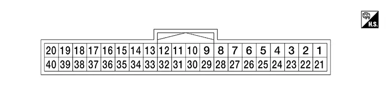
PHYSICAL VALUES
|
Terminal No. (Wire color) |
Description |
Condition |
Value (Approx.) |
|||
|---|---|---|---|---|---|---|
|
Signal name |
Input/ Output |
|||||
|
(+) |
(-) |
|||||
|
1 (GR) |
Ground |
Battery power |
Input |
Push-button ignition switch OFF |
Battery voltage |
|
|
3 (BR) |
Ground |
Intelligent Key warning buzzer output |
Output |
Intelligent Key warning buzzer |
Sounding Note:
The pulse cycle changes depending on buzzer sounds. |
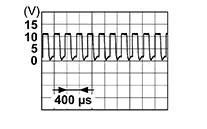 |
|
Not sounding |
0 V |
|||||
|
41 (LG) |
Ground |
Front door request switch LH |
Input |
Front door request switch LH |
ON (pressed) |
0 V |
|
OFF (not pressed) |
Battery voltage |
|||||
|
6 (LA/L) |
Ground |
CAN-High |
Input/ Output |
— |
— |
|
|
7 (LA/P) |
Ground |
CAN-Low |
Input/ Output |
— |
— |
|
|
9 (BG) |
Ground |
Push-button ignition switch |
Input |
Push-button ignition switch |
Pressed |
0 V |
|
Not pressed |
Battery voltage |
|||||
|
10 (L) |
Ground |
Push-button ignition switch illumination power supply |
Output |
Push-button ignition switch illumination |
OFF |
0 V |
|
ON |
Battery voltage |
|||||
|
111 (P) |
Ground |
Front door request switch RH |
Input |
Front door request switch RH |
ON (pressed) |
0 V |
|
OFF (not pressed) |
Battery voltage |
|||||
|
19 (R) |
Ground |
NATS antenna |
Input/Output |
Intelligent Key battery is removed and brake pedal is depressed |
When a registered Intelligent Key backside is contacted to push-button ignition switch |
0 V |
|
Other than above |
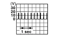
|
|||||
|
Inside key antenna |
Output |
Push-button ignition switch OFF |
When Intelligent Key is in the passenger compartment |
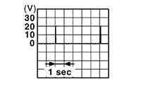
|
||
|
When Intelligent Key is not in the passenger compartment |
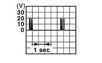
|
|||||
|
20 (G) |
Ground |
NATS antenna |
Input/Output |
Intelligent Key battery is removed and brake pedal is depressed |
When a registered Intelligent Key backside is contacted to push-button ignition switch |
0 V |
|
Other than above |
|
|||||
|
29 (LA/B) |
Ground |
Ground |
— |
Push-button ignition switch OFF |
0 V |
|
|
31 (LA/R) |
Ground |
Outside key antenna (rear door RH) |
Output |
When the front door request switch RH is operated with push-button ignition switch ON |
When Intelligent Key is in the antenna detection area |
|
|
When Intelligent Key is not in the antenna detection area |
|
|||||
|
32 (LA/SB) |
Ground |
Outside key antenna (rear door RH) |
Output |
When the front door request switch RH is operated with push-button ignition switch ON |
When Intelligent Key is in the antenna detection area |
|
|
When Intelligent Key is not in the antenna detection area |
|
|||||
|
33 (LA/G) |
Ground |
Inside key antenna (trunk room) |
Output |
Push-button ignition switch OFF |
When Intelligent Key is in the passenger compartment |
|
|
When Intelligent Key is not in the passenger compartment |
|
|||||
|
34 (LA/L) |
Ground |
Inside key antenna (trunk room) |
Output |
Push-button ignition switch OFF |
When Intelligent Key is in the passenger compartment |
|
|
When Intelligent Key is not in the passenger compartment |
|
|||||
|
35 (LA/V) |
Ground |
Outside key antenna (rear door LH) |
Output |
When the front door request switch LH is operated with push-button ignition switch ON |
When Intelligent Key is in the antenna detection area |
|
|
When Intelligent Key is not in the antenna detection area |
|
|||||
|
36 (LA/P) |
Ground |
Outside key antenna (rear door LH) |
Output |
When the front door request switch LH is operated with push-button ignition switch ON |
When Intelligent Key is in the antenna detection area |
|
|
When Intelligent Key is not in the antenna detection area |
|
|||||
|
37 (LA/Y) |
Ground |
Outside key antenna (rear bumper) |
Output |
When the trunk lid opener request switch is operated with push-button ignition switch ON |
When Intelligent Key is in the antenna detection area |
|
|
When Intelligent Key is not in the antenna detection area |
|
|||||
|
38 (LA/W) |
Ground |
Outside key antenna (rear bumper) |
Output |
When the trunk lid opener request switch is operated with push-button ignition switch ON |
When Intelligent Key is in the antenna detection area |
|
|
When Intelligent Key is not in the antenna detection area |
|
|||||
1: With request switch
Other materials:
U2140-87 Can Comm Err (ecm)
Dtc Description
DTC Description
DTC DETECTION LOGIC
DTC No.
CONSULT screen terms
(Trouble diagnosis content)
DTC detection condition
...
P00d2 Ho2s2 Heater
Dtc Description
DTC Description
DTC DETECTION LOGIC
DTC
CONSULT screen terms
(Trouble diagnosis
content)
DTC detection
conditi ...
Preparation. Preparation
Preparation
Special Service Tool
Special Service Tool
The actual shape of the tools may differ from those
illustrated here.
Tool number
(TechMate No.)
Tool name
...