Nissan Sentra B18 (2020-2025) Service Manual: Cooling Fan
Exploded View
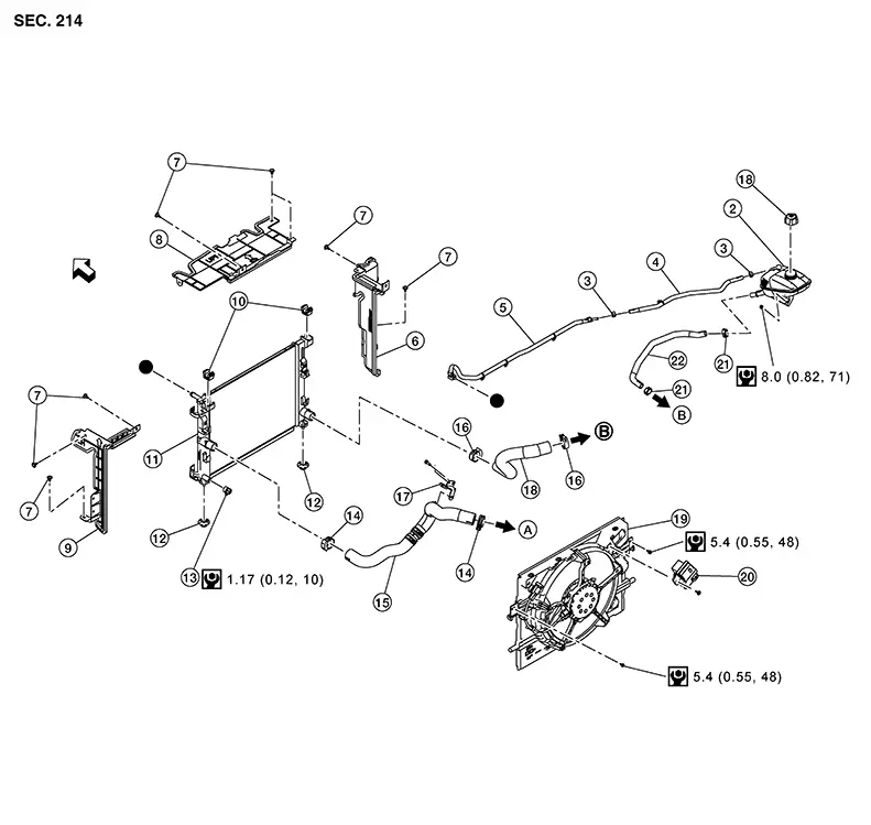
Exploded View
|
1. |
Reservoir tank cap |
2. |
Reservoir tank |
3. |
Clamp |
|
4. |
Reservoir tank hose A |
5. |
Reservoir tank hose B |
6. |
Air guide (RH) |
|
7. |
Clip |
8. |
Air guide (upper) |
9. |
Air guide (LH) |
|
10. |
Mounting rubber (upper) |
11. |
Radiator assembly |
12. |
Mounting rubber (lower) |
|
13. |
Drain cock |
14. |
Clamp |
15. |
Radiator hose (upper) |
|
16. |
Clamp |
17. |
Bracket |
18. |
Radiator hose (lower) |
|
19. |
Cooling fan assembly |
20. |
Cooling fan control module |
21. |
Clamp |
|
22. |
Water hose |
A. |
To water outlet. Refer to Exploded View. |
B. |
To water inlet. Refer to Exploded View. |
|
|
: Front |
 : Indicates that the part is connected at points with the same
symbol in the actual Nissan Sentra vehicle.
: Indicates that the part is connected at points with the same
symbol in the actual Nissan Sentra vehicle.
Removal and Installation
Removal and Installation
REMOVAL
Remove the air cleaner assembly and air inlet duct. Refer to Removal and Installation.
Remove reservoir tank hose A and reservoir tank hose B retainers from cooling fan assembly.
Disconnect the harness connectors from the cooling fan module and cooling fan.
Remove the harness retainers from the cooling fan assembly.
Drain the engine coolant. Refer to Draining.
Remove the front under cover. Refer to Removal and Installation.
Remove the radiator hose (lower) from the radiator.
Remove bolt
(A), release pawl and remove the cooling fan assembly (1). 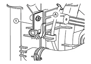 Note:
Note: 
LH shown, RH similar.
|
|
: Pawl |

Remove screw and remove the cooling fan module from the cooling fan assembly (if necessary).
INSTALLATION
Installation is in the reverse order of removal.
-
Refill the engine coolant. Refer to Refilling.
Other materials:
P0139 Ho2s2
Dtc Description
DTC Description
The heated oxygen sensor 2 has a much longer switching time
between rich and lean than the air fuel ratio (A/F) sensor 1. The oxygen storage
capacity of the three way catalyst 1 causes the longer switching time. To judge
the malfunctions of heated oxy ...
P2297 Air Fuel Ratio Sensor 1
Dtc Description
DTC Description
DTC DETECTION LOGIC
DTC
CONSULT screen terms
(Trouble diagnosis
content)
DTC detection
conditi ...
Uniform tire quality grading
DOT (Department of Transportation) Quality Grades apply to all passenger car
tires and are intended to provide comparative information in addition to meeting
federal safety requirements.
Where applicable, these quality grades are molded into the tire sidewall between
the tread shoulder and th ...